
Terminal electric tape automatic winding apparatus

A technology of insulating tape and winding device, which is used in transportation and packaging, equipment for connecting/terminating cables, sending objects, etc., can solve problems such as low work efficiency, a lot of manpower and material resources, and unsatisfactory winding quality.

Inactive Publication Date: 2018-05-18
杨雪锋
View PDF9 Cites 8 Cited by
  • Summary
  • Abstract
  • Description
  • Claims
  • Application Information

AI Technical Summary

Problems solved by technology

[0003] At present, the connection of the insulating tape in the process of connecting the wire ends is done manually by workers. First, the worker sticks one end of the insulating tape on the wire core, and then stretches the insulating tape to make it elastically deformed, and the stretched state The insulating tape is wound on the wire core several times until the insulating tape covers the core several layers, then the insulating tape is cut off to complete the winding of the insulating tape. In the process of manually winding the insulating tape, not only a lot of manpower and material resources are required, Moreover, the work efficiency is extremely low. Due to the different degrees of elastic deformation of the insulating tape, the quality of the winding is not ideal. If it is serious, it will cause leakage and short circuit. A lot of tapes and wires are wasted, and the overall project progress will be delayed, so it is imperative to invent an automatic winding device for terminal insulating tape

Method used


Image

  • Terminal electric tape automatic winding apparatus
  • Terminal electric tape automatic winding apparatus
  • Terminal electric tape automatic winding apparatus

Examples


Embodiment Construction

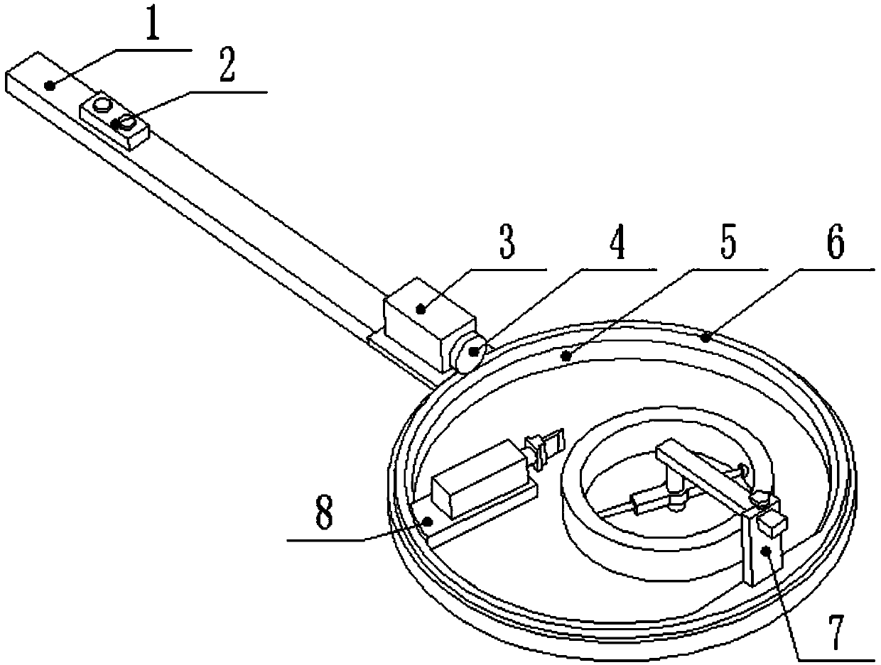
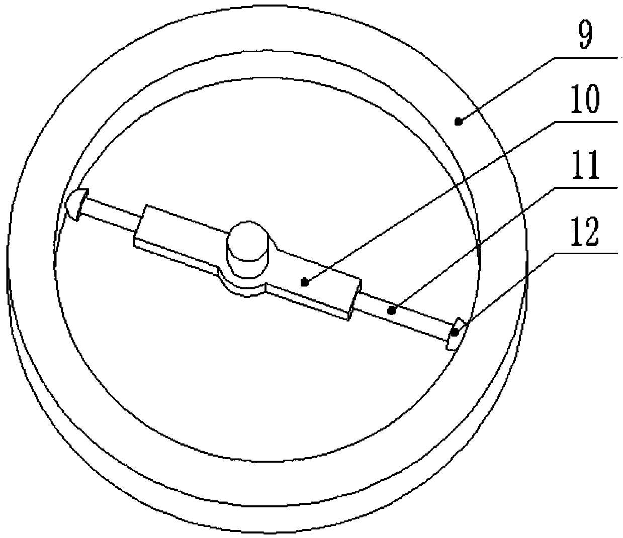
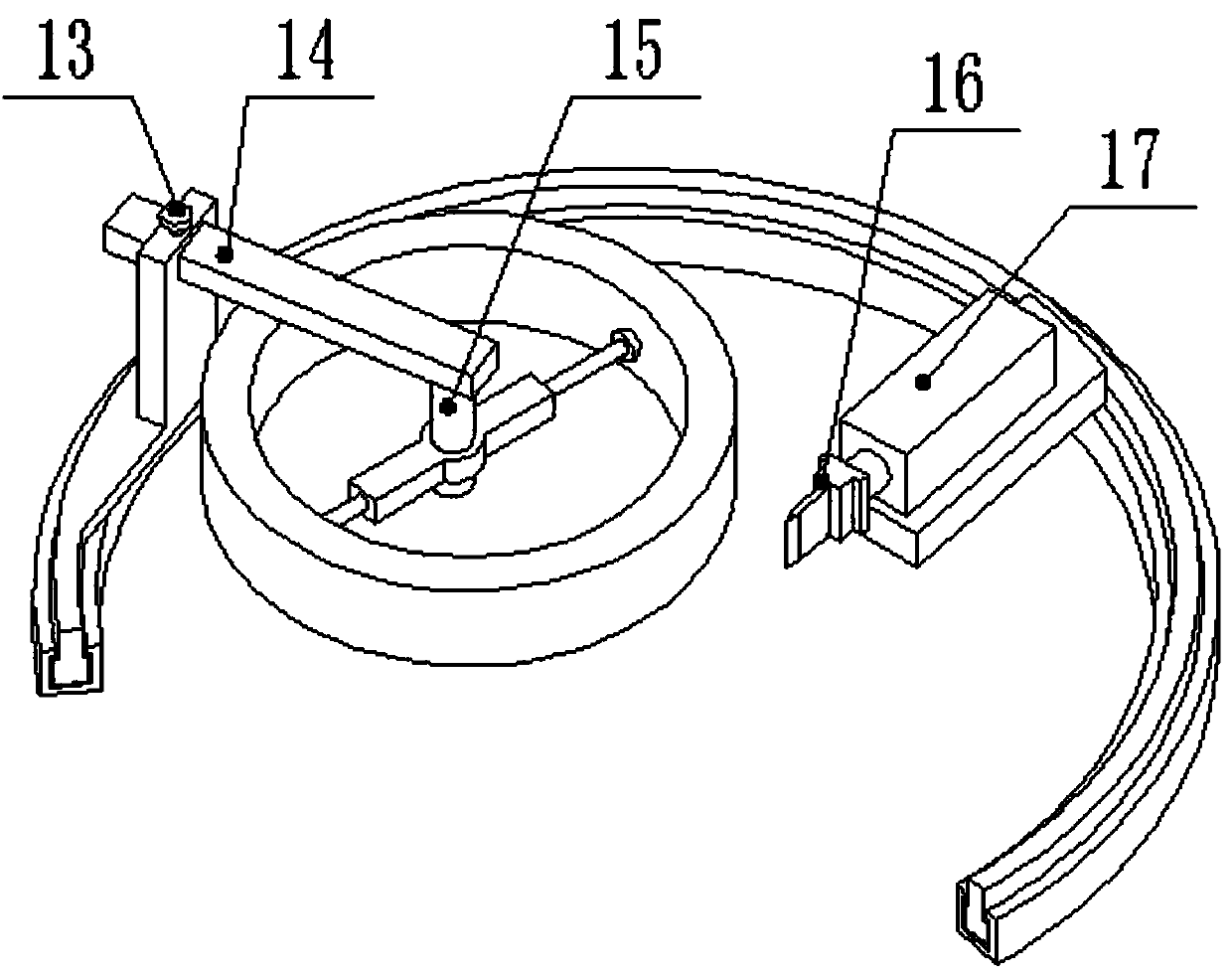
[0017] The present invention is achieved through the following technical solutions: an automatic winding device for insulating tape at the end, including a hand-held base frame 1, a controller 2, a motor 3, a friction wheel 4, a sliding track 5, a rotating ring 6, a first bracket 7, Second support 8, insulating tape roll 9, damping wheel 10, fixed screw rod 11, antiskid ball 12, fixed bolt 13, the 3rd support 14, damping shaft 15, blade 16 and electromagnet 17, described hand-held base frame 15 and sliding The track is connected, and the user can extend the device into some difficult-to-reach positions through the handheld base frame 1. The controller 2 is installed on the handheld base frame, which is fixed at the end of the handheld base frame 1 near the handle, and is used to control the motor. 3 and the action of the electromagnet 17, the motor 3 is installed on the hand-held base frame 1, and it is fixed on the other end of the hand-held base frame 1 away from the handle, ...


PUM


Abstract

The invention discloses a terminal electric tape automatic winding apparatus, and belongs to the field of engineering daily tools. A handheld base frame is connected with a sliding rail, a controlleris installed on the handheld base frame, and a friction wheel is installed on a motor. A rotating ring is arranged in the sliding rail, and an insulating tape roll is fixed on an anti-slip ball. A fixed screw rod is installed on the two sides of a damping wheel, an anti-skid ball is arranged at one end of the fixed screw rod, a damping shaft is installed below one end of a third support, and an electromagnet is installed above a second support. The friction wheel is driven to rotate through rotation of the motor, so that the friction wheel drives the rotating ring to rotate, and the process ofmanual winding of workers is replaced. Damping rotation is carried out through the damping wheel and the damping shaft, so that the insulation adhesive tape wound on the wire core is ensured to havethe same elastic deformation degree, and the winding stress of the adhesive tape is uniform. The work of workers is replaced, and the winding quality and efficiency of the adhesive tape are improved.

Description

technical field [0001] The invention relates to an automatic winding device for insulating tape at the end, specifically a device that puts the wire core into a rotating ring, and drives the friction wheel to rotate through a motor, so that the rotating ring rotates, so that the insulating tape is evenly stressed and wound on the wire core The device on the utility model belongs to the field of engineering daily tools. Background technique [0002] With the rapid development of my country's economy, the number of engineering projects is increasing. The development and construction of engineering projects is inseparable from the construction of circuits, and the connection of wire ends in the process of circuit construction is an extremely critical step, which requires a large number of workers. Time is spent on the connection of the wire end, and the winding process of the insulating tape has taken up most of the time for the wire end connection. [0003] At present, the con...

Claims


Application Information

Patent Timeline
IPC IPC(8): H02G1/14B65H35/07
CPCH02G1/14B65H35/0033B65H2701/377
Inventor 杨雪锋
Owner 杨雪锋
Learn More