Device and Method for Testing an Electrical Power Branch Circuit

a technology for testing circuits and circuit breakers, applied in measurement devices, parameter calibration/setting, instruments, etc., can solve problems such as large disparity in short-circuit and ground fault protection provided from premises to premises, no test device is capable, and receives rapid breakers

Inactive Publication Date: 2008-04-10
KO INSTR
View PDF6 Cites 29 Cited by
  • Summary
  • Abstract
  • Description
  • Claims
  • Application Information

AI Technical Summary

Benefits of technology

[0010] The invention may further comprise a zero-crossing detection system and method that eliminates the uncertainty due to voltage fluctuation found in conventional zero-crossing detectors.
[0013] The short-circuit and fault current paths employ a fuse or another overcurrent protective device that is rated to protect the circuit-under-test from prolonged exposure to the potential hazards associated with sustained exposure to short-circuit and / or fault current in the event of catastrophic failure of all controls and other overcurrent protection devices in the circuit-under-test.

Problems solved by technology

This limitation results in available fault current at many outlets on these circuits that is insufficient to trigger the magnetic (1-cycle) response mechanism in the circuit breakers installed to protect them, leaving only the long-time (thermal) pick-up response of the circuit breaker as protection for parallel short-circuit or ground-fault overcurrent.
Because short-circuits or ground-faults have been shown in research to cause rapid ignition, the potential for an unsafe condition can result at an outlet at which the above condition exists.
However, the product standard does not yet require an instantaneous response, and there is no test device that is capable of verifying in a practical and convenient manner that an installed equipment-grounding conductor and the circuit breaker of any branch circuit meet this requirement of the NEC, or that a given installed outlet will receive a rapid breaker response to a short-circuit or ground-fault.
The lack of standardization of this particular breaker response in combination with a wide variation of available short-circuit and fault current at 120-volt outlets has resulted in a situation where there is a great disparity in short-circuit and ground-fault protection provided from premises to premises and even outlet to outlet in both the installed building infrastructure and in new buildings as they are wired today.

Method used


Image

  • Device and Method for Testing an Electrical Power Branch Circuit
  • Device and Method for Testing an Electrical Power Branch Circuit
  • Device and Method for Testing an Electrical Power Branch Circuit

Examples


Embodiment Construction

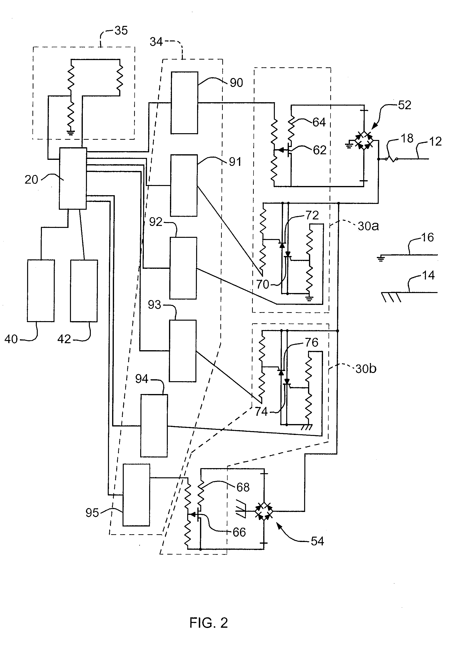
[0025] In a preferred embodiment, the inventive device and method is included as a part of a hand-held tester plugged into 120 VAC receptacle outlet or otherwise electrically connected to a 120 VAC outlet protected by a 15 or 20 Amp circuit breaker. In a preferred embodiment, the device is powered from the branch circuit, and has an internal battery (not shown in the drawings) for back-up power to maintain data integrity and continuity of operation when a breaker is tripped. The circuitry is protected by an overcurrent protective device (e.g., a fuse) with characteristics which allow one cycle bursts of predetermined current levels, but will operate to open the circuit before conductor overheating in the branch circuit-under-test occurs. For example, a 15 A fuse may be used in the preferred embodiment of FIG. 2.

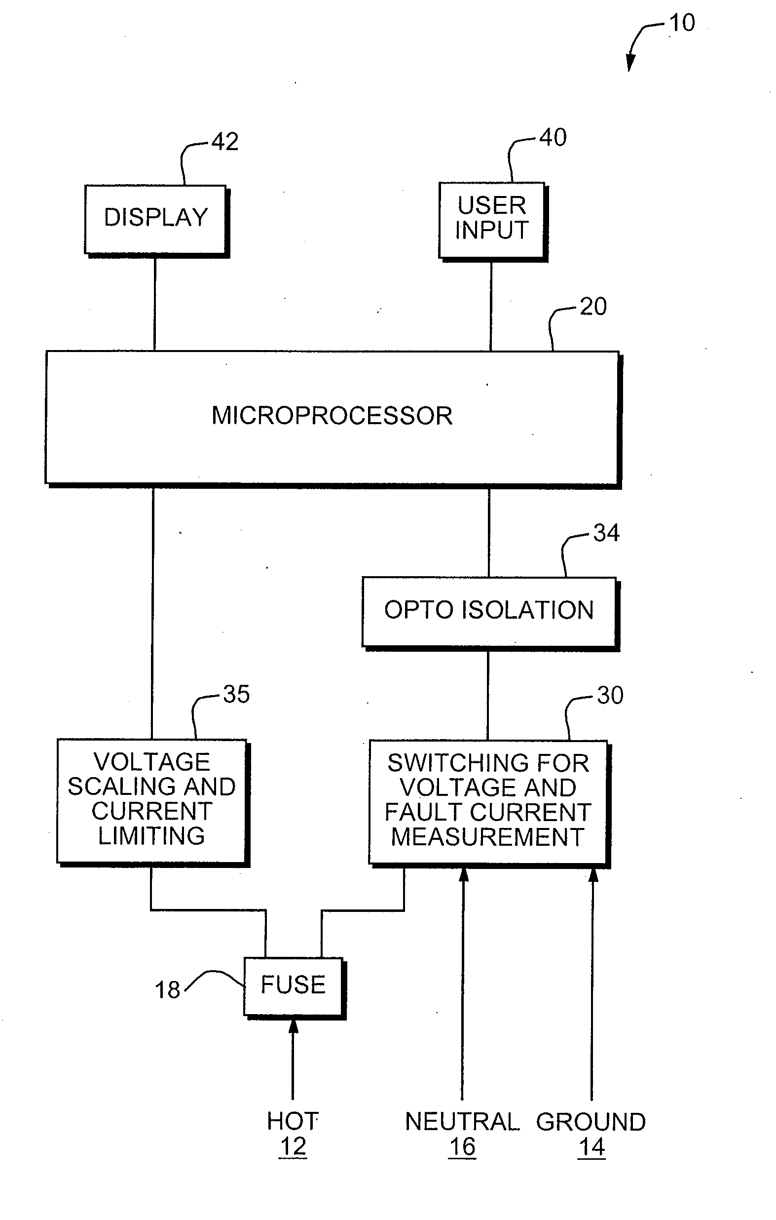
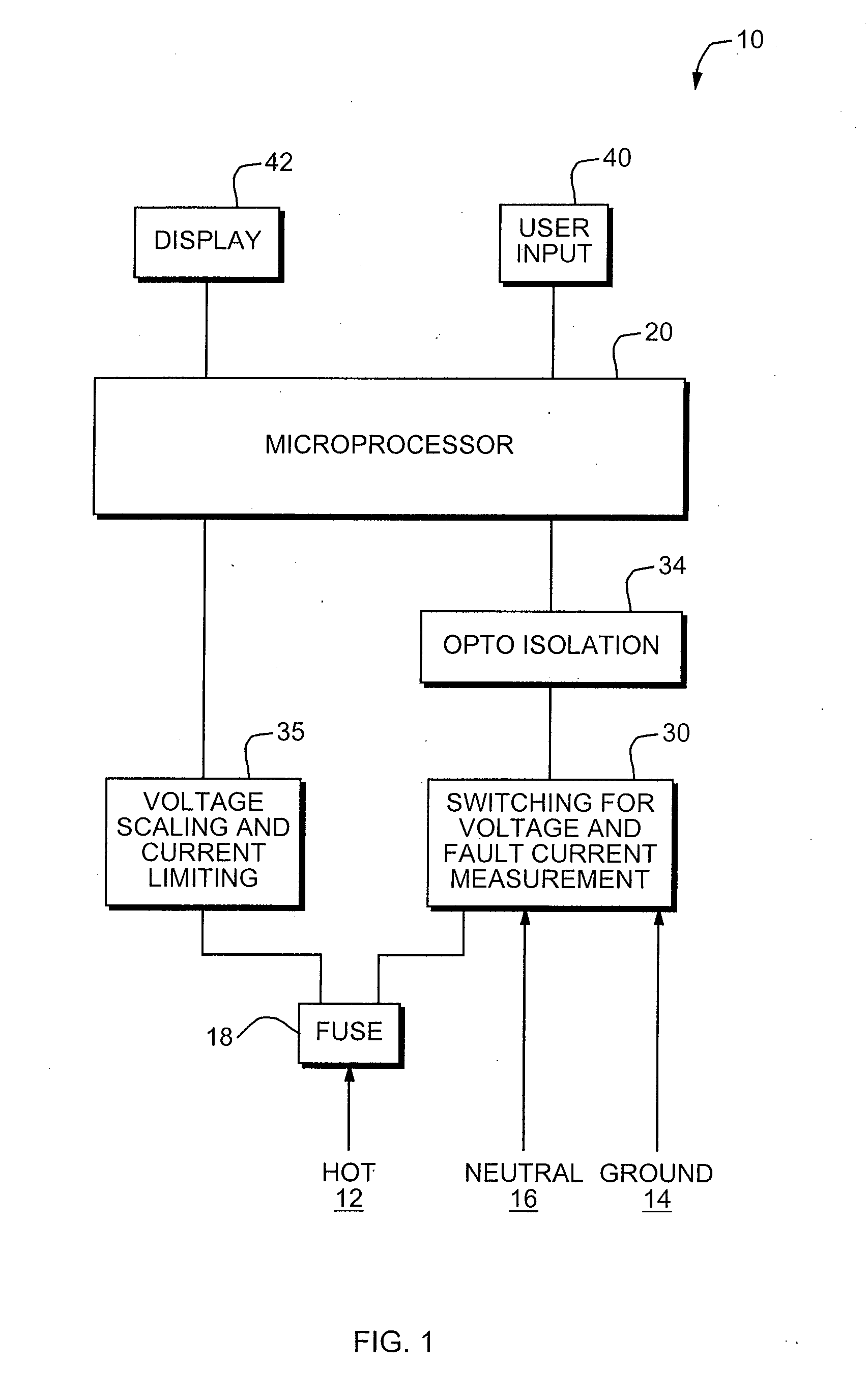
[0026]FIG. 1 is a functional block diagram of an embodiment of the device of the invention that can also accomplish the method of the invention. System 10 makes circuit and ...


PUM


Abstract

A device and method for testing an electrical power branch circuit that includes hot, neutral and protective ground conductors and that carries alternating current. The device includes circuitry for determining the total available short-circuit current that can be carried by the neutral conductor, circuitry for determining the total available ground-fault current that can be carried by the protective ground conductor, and circuitry that, based on at least one of the determined short-circuit current and the determined ground-fault current, applies a short-circuit or ground-fault current to the electrical power branch circuit.

Description

CROSS-REFERENCE TO RELATED APPLICATIONS [0001] This application claims priority of Provisional applications 60 / 828,639 filed on Oct. 7, 2006, 60 / 828,640 filed on Oct. 7, 2006 and 60 / 870,127 filed on Dec. 15, 2006. The entire contents of these three provisional applications are incorporated herein by reference.FIELD OF THE INVENTION [0002] This invention relates to a device for testing circuits and circuit breakers. BACKGROUND OF THE INVENTION [0003] Standard circuit breakers of the type found in residential, institutional and light commercial settings are thermal / magnetic in operation. Requirement 250.4(A)(5) of the National Electrical Code (NEC) and the expectation of the electrical industry is that a circuit breaker should respond as rapidly as possible to a short-circuit or a ground-fault. The magnetic portion of the breaker is designed to react within 1 cycle on 60 Hz systems to the higher levels of overcurrent produced by parallel fault conditions such as short-circuits or grou...

Claims


Application Information

Patent Timeline
Patent Type & Authority Applications(United States)
IPC IPC(8): G01R31/327
CPCG01R31/3277H02H3/08H02H3/006
Inventor WAITE, ROBERT K.KELEHER, PAUL A.
Owner KO INSTR
Why Eureka
Try Eureka