
Diffuser plate having multi-aspheric structure

Inactive Publication Date: 2008-04-10
ENTIRE TECH CO LTD
View PDF3 Cites 10 Cited by
  • Summary
  • Abstract
  • Description
  • Claims
  • Application Information

AI Technical Summary

Benefits of technology

[0004]It is a primary object of the present invention to form an aspheric structure on a plate for improving the brightness. In addition, the present invention discloses a multi-aspheric structure to avoid the non-uniformity of the single aspheric structure.
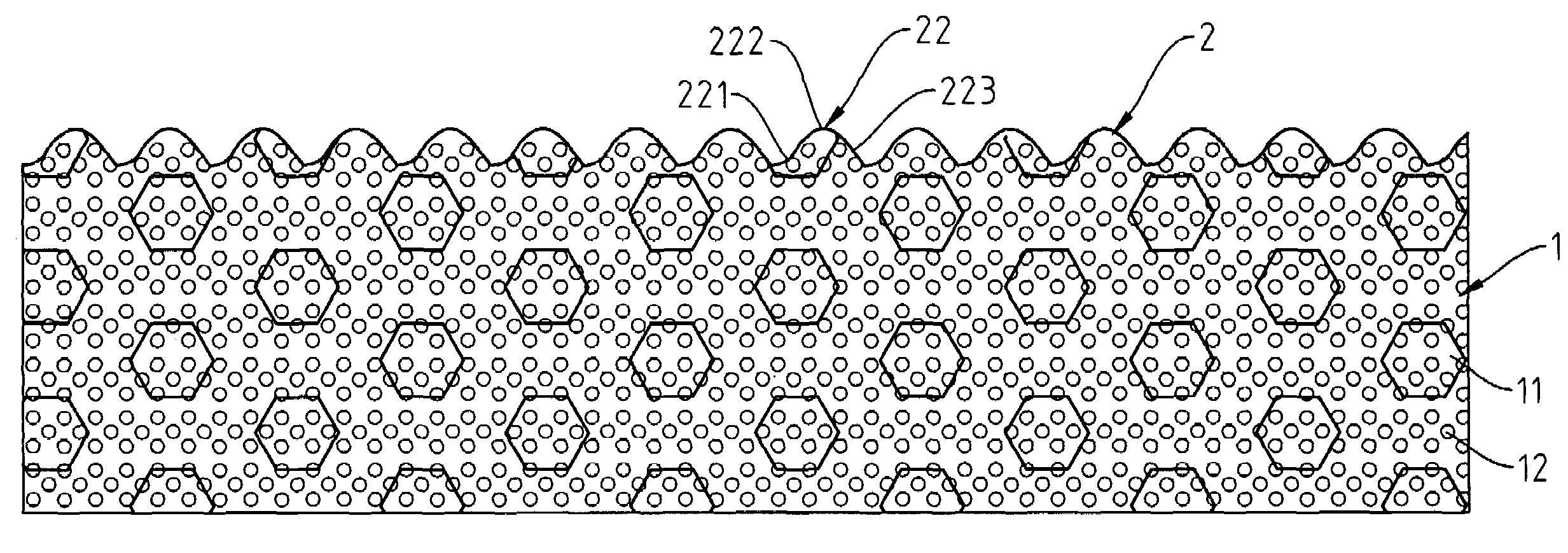
[0005]In order to achieve the above-mentioned object, a diffuser plate having a multi-aspheric structure of the present invention comprises a plate and at least one aspheric microstructure. The plate is made of a transparent polymer and doped with a UV absorbent and several diffusion particles. The aspheric microstructure is formed on at least one surface of the plate and comprises a plurality of aspheric bars having at least one kind of arrangements. The aspheric bars have a curviform profile consisting of at least one curve line. By the use of the aforesaid structure, the present invention can improve the conventional problems and can provide the advantages including high light transmission rate, raised diffusion capability, improved brightness, and uniform light beams.

Problems solved by technology

It means that the brightness distribution of the backlight module is very poor when the human eyes look at different positions of the backlight module.
It is apprehensible that the upper light beams of the lamp are allowed to enter the eyes directly, but the farther light beams can not be diffused to the dark region beside the lamp and the light beams can not be focused into the retinas of the eyes.
As a result, almost every direct backlight module can not provide uniform brightness in the absence of an optical film.
However, the obtained brightness value may be decreased significantly because of the conservation of energy and the imperfect design.
In particular, with the decrease of lamps in the 32 inches LCD TV, for example, from sixteen lamps to twelve lamps, the brightness and uniformity of the LCD monitor is further reduced, which further reduces the desire of the consumer for buying the LCD monitor.
The lamp number of the existing backlight module of the LCD monitor is reduced for the purpose of reducing the production cost, which enlarges the distances among the lamps and makes the MURA defects become more serious.
As a result, the diffusion angle of the light beam is so large that the human eyes can only sense partial brightness because the human eyes have limited filed of view.
However, the increased thickness violates the purpose of forming thinner backlight module.

Method used


Image

  • Diffuser plate having multi-aspheric structure
  • Diffuser plate having multi-aspheric structure
  • Diffuser plate having multi-aspheric structure

Examples


Embodiment Construction

[0018]Referring to FIG. 4, a diffuser plate having a multi-aspheric structure in accordance with a first preferred embodiment of the present invention comprises a plate 1 and at least one aspheric microstructure 2. The configuration of the aspheric microstructure 2 is determined by an aspheric equation mentioned in the traditional optics.

[0019]The plate 1 is made of a transparent polymer selected from a group consisting of poly(methylmethacrylate) (PMMA), polycarbonate (PC), (methylmethacrylate)styrene (MS) and polystyrene (PS). The plate 1 is integrally formed by an extrusion process for forming a plurality of aspheric microstructures 2 on at least one surface of the plate 1. In addition, the plate 1 has a UV absorbent 11 doped therein to prevent the direct UV light irradiation from causing the plate 1 to generate the phenomena of photoyellowing and cracking. In addition, the plate 1 has several diffusion particles 12 doped therein, wherein the diffusion particles 12 are made of a ...


PUM


Abstract

A diffuser plate having a multi-aspheric structure comprises a plate and at least one aspheric microstructure. The plate is made of a transparent polymer. The plate is doped with a UV absorbent and several diffusion particles. The aspheric microstructure is formed on at least one surface of the plate. By the use of the aforesaid structure, the present invention can improve the conventional problems and provide the advantages including high light transmission rate, raised diffusion capability, improved brightness, and uniform light beams.

Description

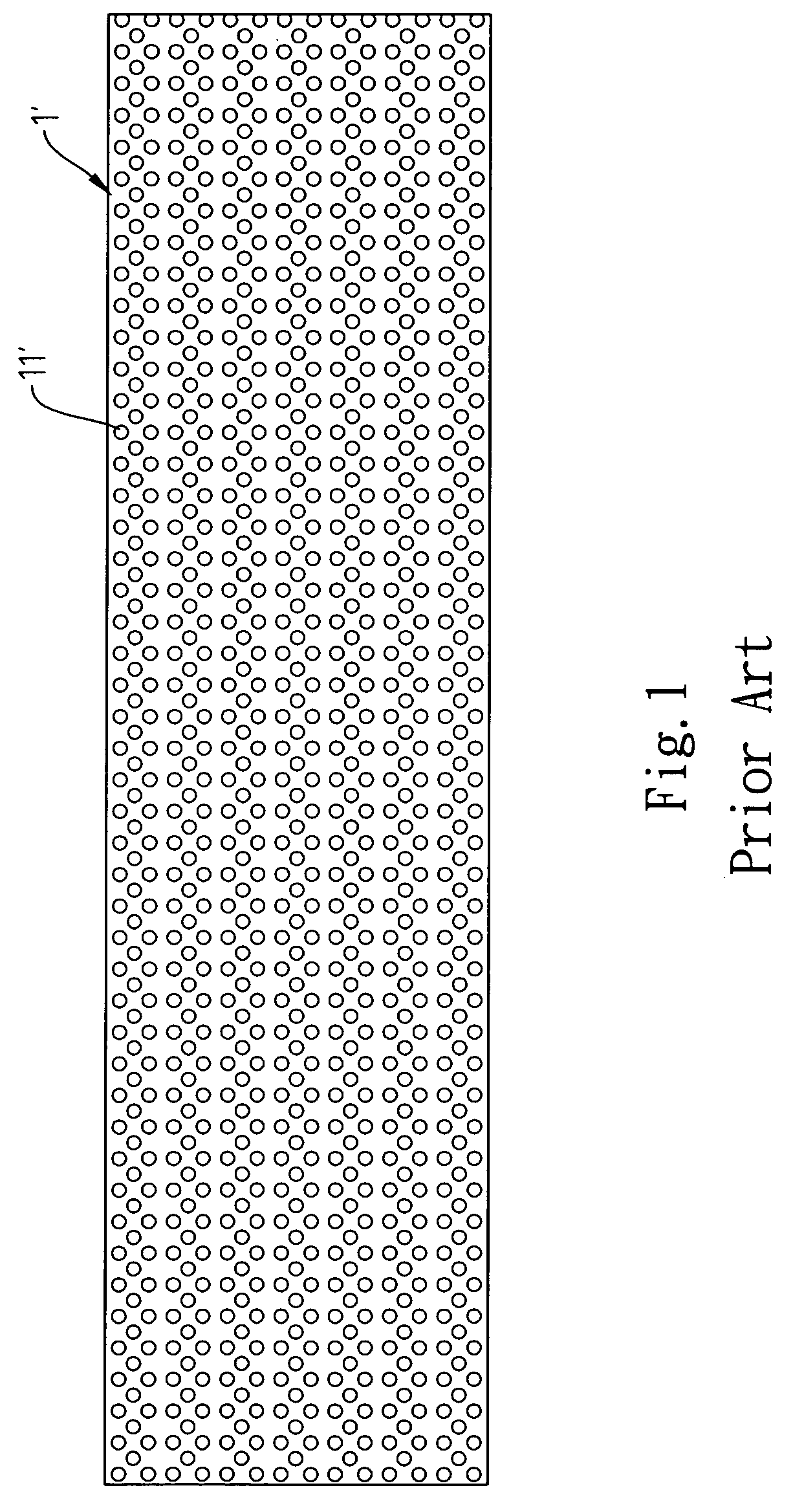
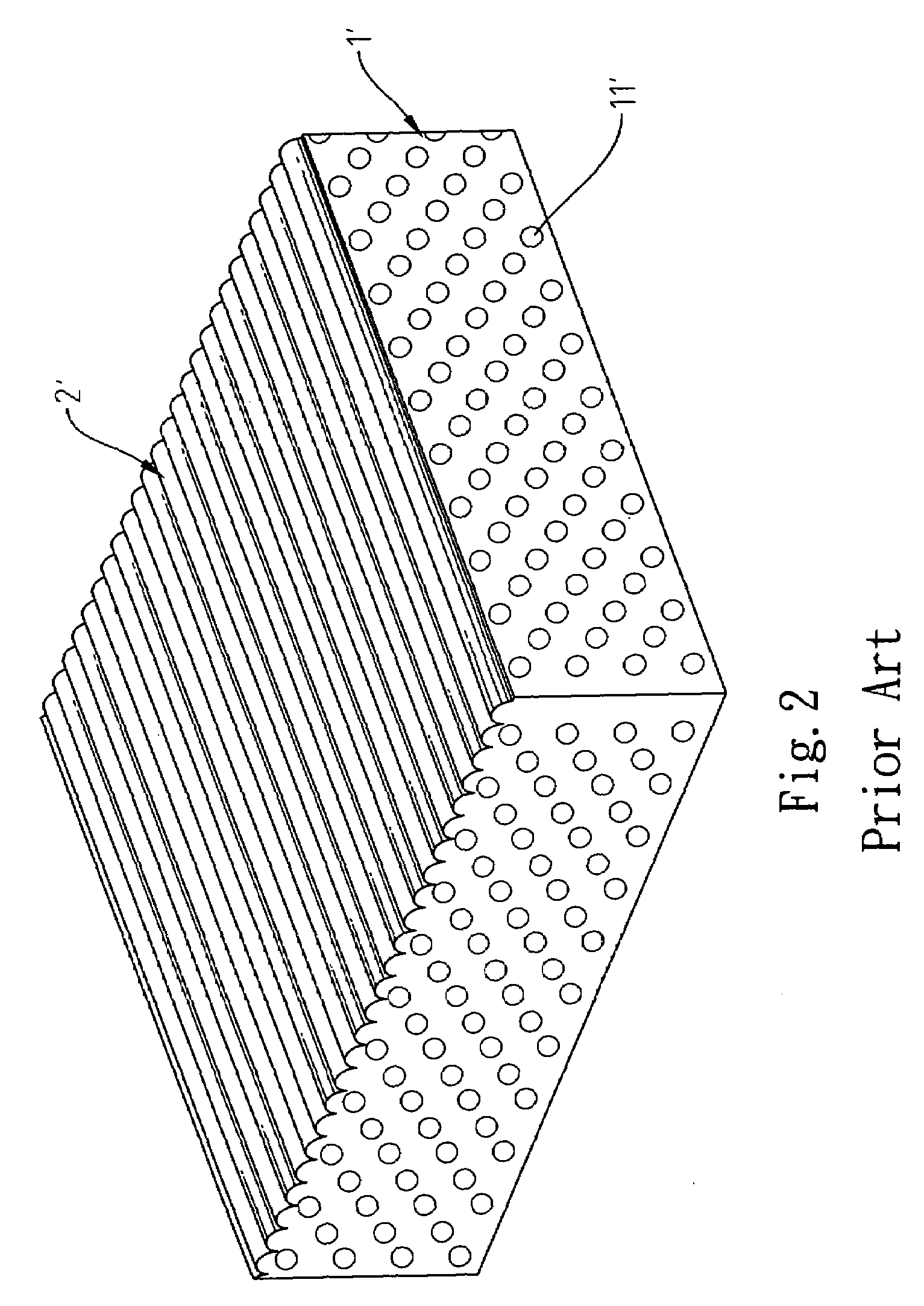
FIELD OF THE INVENTION[0001]The present invention relates to a diffuser plate having a multi-aspheric structure, and more particularly to a diffuser plate that utilizes a plate and at least one aspheric microstructure to provide many advantages including high light transmission rate, raised diffusion capability, improved brightness, and uniform light beams.BACKGROUND OF THE INVENTION[0002]Generally speaking, a general diffuser plate is applied to a LCD monitor so as to allow a cold cathode fluorescent lamp (CCFL) of the LCD monitor to diffuse the light beams uniformly, thereby obtaining a uniform area light source. Referring to FIG. 1 and FIG. 2, a diffuser plate is treated with two methods. In the first method, a diffuser plate 1′ is doped with diffusion particles 11′ so as to reflect, refract or scatter the light beams by the diffusion particles 11′. In the second method, a diffuser plate 1′ is doped with diffusion particles 11′ and a refraction structure 2′ is formed on the top o...

Claims


Application Information

Patent Timeline
IPC IPC(8): G02B5/02
CPCG02B5/003G02B13/18G02B5/0278G02B5/0242
Inventor LIN, CHAO-YING
Owner ENTIRE TECH CO LTD
Learn More