
Nuclear reactor fuel assemblies

a fuel assembly and nuclear reactor technology, applied in nuclear engineering problems, nuclear elements, greenhouse gas reduction, etc., can solve the problems of small gap between baffle structure plates, small lateral distortion of fuel assembly structures, and difference in thermal expansion between materials, so as to increase burn-up and resident time in core, enhance fuel assembly dimensional stability, and reduce the probability of incomplete rod cluster control assembly

Inactive Publication Date: 2008-04-10
WESTINGHOUSE ELECTRIC CORP
View PDF13 Cites 29 Cited by
  • Summary
  • Abstract
  • Description
  • Claims
  • Application Information

AI Technical Summary

Benefits of technology

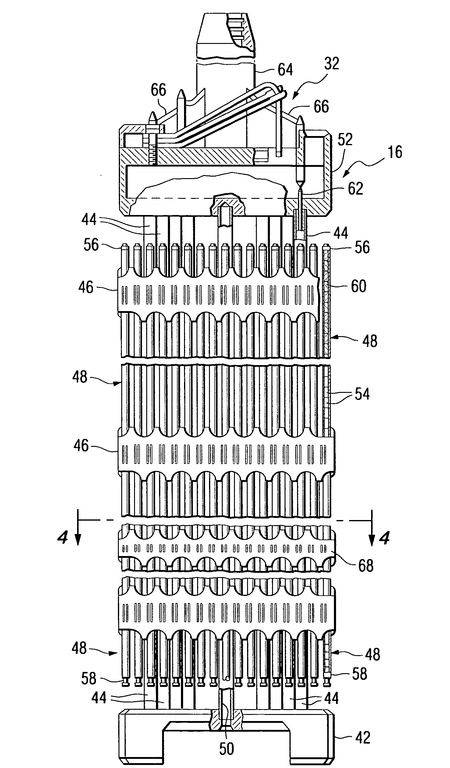
[0015]This invention achieves the foregoing objectives by enhancing the fuel assembly dimensional stability to support aggressive fuel management, i.e., increase burn-up and resident time in-core, and decrease the probability of an incomplete rod cluster control assembly insertion, a handling accident and other consequences of fuel assembly bow. The fuel assembly dimensional stability is achieved by enhancing the fuel assembly skeleton lateral stiffness through the introduction of an additional bulge joint between the control rod guide thimble and spacer grid sleeve. The additional bulge decreases “free play” in the bulge joint, increasing the skeleton lateral stiffness.

Problems solved by technology

These bolts sometimes become loose, thereby developing a small gap between the baffle structure plates.
These lateral hydraulic forces in addition to the turbulence of the coolant rising upwardly through the core as a result of mixing vanes on the fuel assembly grids, tend to cause small lateral distortions of the fuel assembly structures.
The difference in thermal expansion between these materials, as well as radiation growth factors adds to the force acting on the fuel assemblies that cause the lateral distortions.
The only upper limit on the total magnitude of such distortions is the summation of the lateral clearances between the fuel assemblies.
Such distortions are undesirable because they may complicate refueling, introduce slight variations in local power density by virtue of the uneven water gap between assemblies, and may result in incomplete control rod insertions.
Otherwise, clearances between irradiated assemblies will become so small that withdrawing and inserting individual assemblies during refueling may become difficult.
Although such a grid would limit bowing, it is not a desirable solution for two reasons.
First, the replacement of even a single Zircaloy grid with one of stainless steel would increase parasitic neutron absorption.
Second, the greater lateral stiffness of stainless steel grids relative to Zircaloy, coupled with the lower lateral clearance of the stainless steel grids, would cause impact loads associated with seismic disturbances or accident conditions such as loss of coolant, to be concentrated on the stainless grid, thereby necessitating an extremely strong grid.
The consequences of fuel assemblies bow increases with increased burn-up and resident time in the core.

Method used


Image

  • Nuclear reactor fuel assemblies
  • Nuclear reactor fuel assemblies
  • Nuclear reactor fuel assemblies

Examples


Embodiment Construction

[0027]In the following description like reference characters designate like or corresponding parts throughout the several views of the drawings. Also, in the following description, it is to be understood that such terms as “forward”, “rearward”, “left”, “right”, “upwardly”, “downwardly” and the like are words of convenience and are not to be construed as limiting terms.

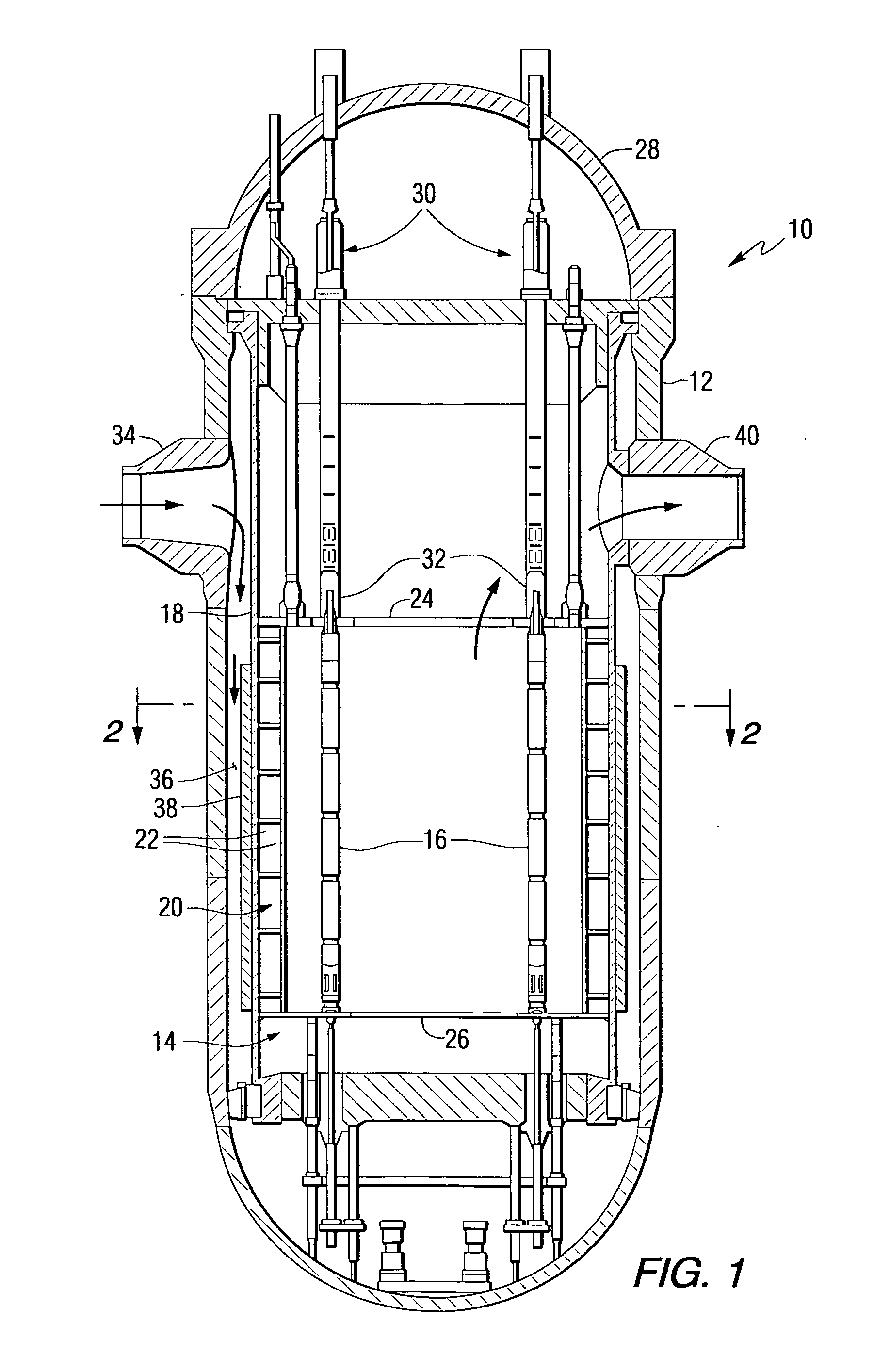
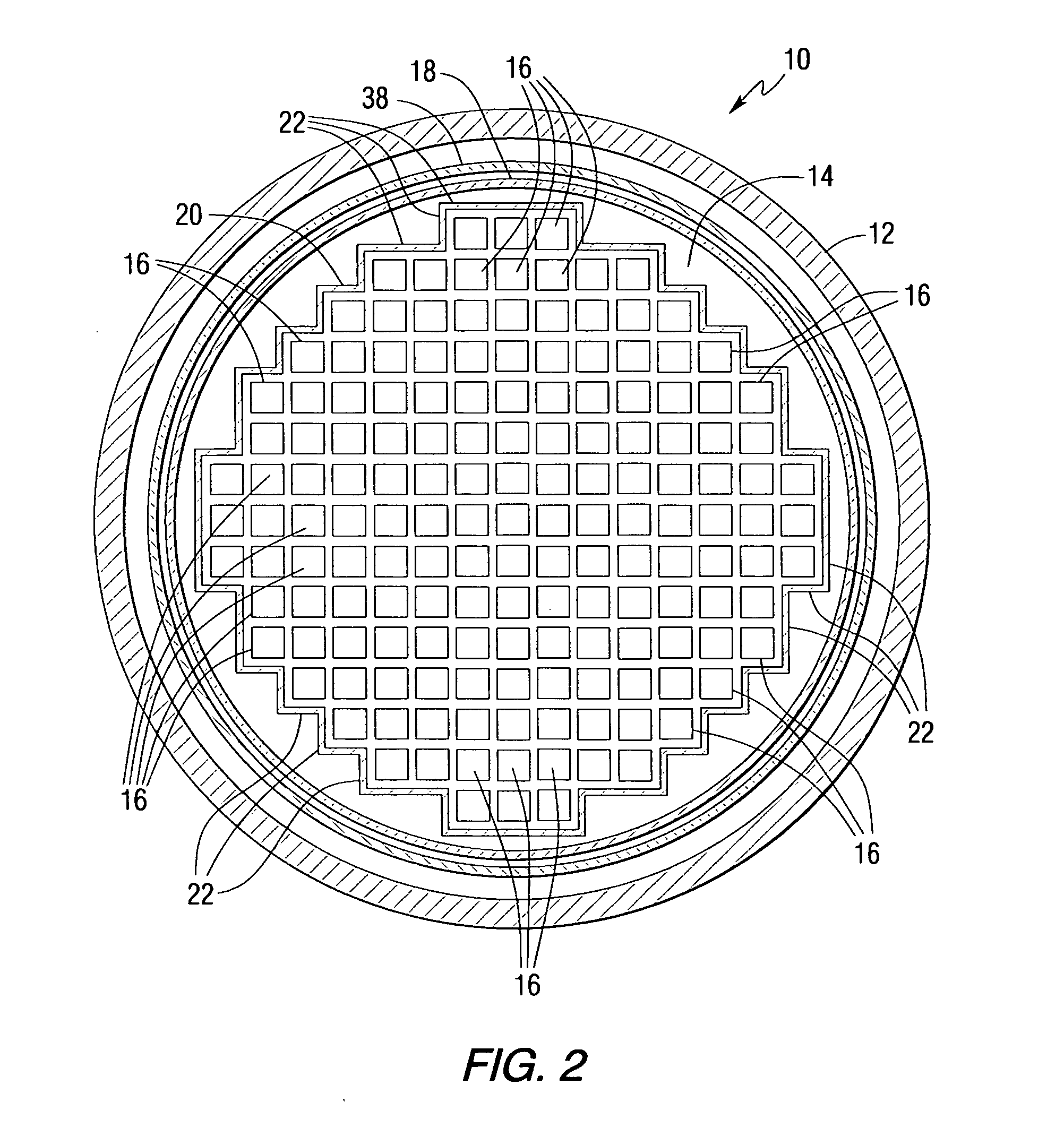
[0028]Referring now to the drawings, and particularly to FIGS. 1 and 2, there is shown a pressurized water nuclear reactor (PWR) being generally designated by reference character 10. The PWR 10 includes a reactor pressure vessel 12 which houses a nuclear reactor core 14 composed of a plurality of elongated fuel assemblies 16. The relatively few fuel assemblies 16 shown in FIG. 1 are for purposes of simplicity only. In actuality, as schematically illustrated in FIG. 2, the core 14 is composed of a great number of fuel assemblies 16.

[0029]Spaced radially, inwardly from the reactor vessel 12 is a generally cylindrical co...


PUM


Abstract

A nuclear fuel assembly having improved dimensional stability to support aggressive fuel management wherein the fuel skeleton lateral stiffness is enhanced by the addition of a second joint attachment between the control rod guide thimble and spacer grid support sleeve.

Description

BACKGROUND OF THE INVENTION[0001]1. Field of the Invention[0002]The present invention relates to nuclear reactor fuel assemblies, and in particular to nuclear fuel assemblies with fortified skeletons that reduce the magnitude of bowing of the assembly which can occur during reactor operation, especially during extended burn-up cycles.[0003]2. Related Art[0004]A typical nuclear power reactor includes a reactor vessel housing a nuclear reactor core. Spaced radially, inwardly from the reactor vessel is a generally cylindrical core barrel and within the barrel is a former and a baffle system (hereafter referred to as the “baffle structure”), which permits transition from the cylindrical barrel to a squared-off, stepped periphery of the reactor core formed by the fuel assemblies arrayed therein.[0005]The reactor core is composed of a large number of elongated fuel assemblies. Each fuel assembly includes a plurality of fuel rods containing fissile material, which reacts to produce heat. T...

Claims


Application Information

Patent Timeline
Patent Type & Authority Applications(United States)
IPC IPC(8): G21G1/06
CPCG21C3/332G21Y2002/206G21Y2002/301Y02E30/40G21Y2004/30G21Y2004/301G21Y2002/304Y02E30/30G21C3/30
Inventor ALESHIN, YURIYSPARROW, JAMES A.
Owner WESTINGHOUSE ELECTRIC CORP
Learn More