Feedback cancellation in a sound system

a technology of acoustical feedback and a sound system, which is applied in the direction of tone control, transducer casing/cabinet/support, electric transducers, etc., can solve the problems of requiring a lot of processing power, and achieve the effect of avoiding unnecessary processing artefacts

Inactive Publication Date: 2008-04-10
PHONIC EAR
View PDF5 Cites 6 Cited by
  • Summary
  • Abstract
  • Description
  • Claims
  • Application Information

AI Technical Summary

Benefits of technology

[0006]A particular advantage of the present invention is the provision of one or more notch-filters engaging in the signal path softly thus avoiding unnecessary processing artefacts.
[0007]A particular feature of the present invention is utilisation of an understanding of the statistical distribution of a speech signal in the frequency domain.
[0008]The above object, advantage and feature together with numerous other objects, advantages and features, which will become evident from below detailed description, are obtained according to a first aspect of the present invention by a sound system for processing acoustical sound and comprising a microphone adapted to convert an acoustical sound to an electrical sound signal, a processor adapted to process said sound signal and to generate a processed sound signal, and a speaker adapted to convert said processed sound signal to a processed acoustical sound, and wherein said processor comprising a calculating unit adapted to calculate a threshold value based on mean magnitude and standard deviation of said sound signal, a FFT unit adapted to transform said sound signal into frequency domain, a peak identification unit adapted to identify a peak in said sound signal in frequency domain and to generate a peak signal, a comparator adapted to compare said threshold value with said peak signal and to generate a control signal identifying frequency of said peak, and a programmable notch-filter unit adapted to receive said control signal and operable to filter out a bandwidth of said sound signal in accordance with said control signal thereby generating said processed sound signal.
[0009]The sound system according to the first aspect of the present invention thus may advantageously utilise the fact that vocal sound has a Gaussian distribution in the time domain and the fact that most energy is of the vocal sound is within one standard deviation from the centre frequency. Hence the sound system may be particularly useful in situations where vocal sound is to be amplified.
[0010]The term “a” is in this context to be construed as one or more, a plurality, or a multiplicity of elements.
[0011]Further, the term “processor” is in this context to be construed as a unit capable of performing a wide range of mathematical processes such as achieved by a microprocessor, a microcontroller, a central processing unit, and / or a digital signal processor. Hence the processor is capable of implementing a transfer function for a sound signal, i.e. providing a required gain in accordance with frequency.

Problems solved by technology

The above referred prior art documents although providing a reduction of the effects of positive feedback require a great number of computations and therefore require a lot of processing power.

Method used


Image

  • Feedback cancellation in a sound system
  • Feedback cancellation in a sound system
  • Feedback cancellation in a sound system

Examples


first embodiment

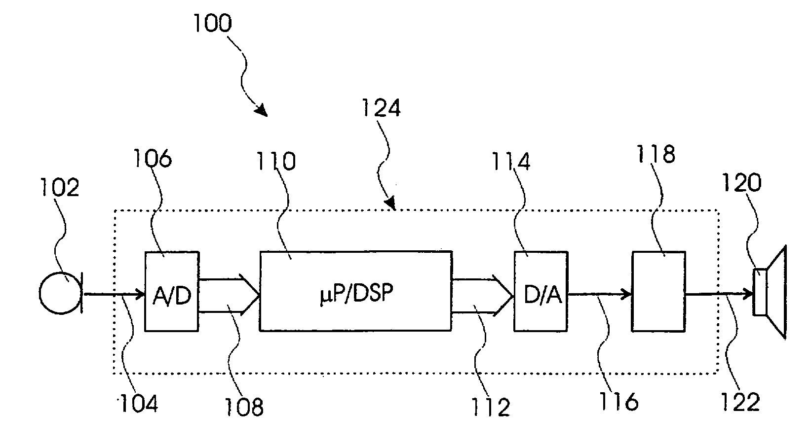
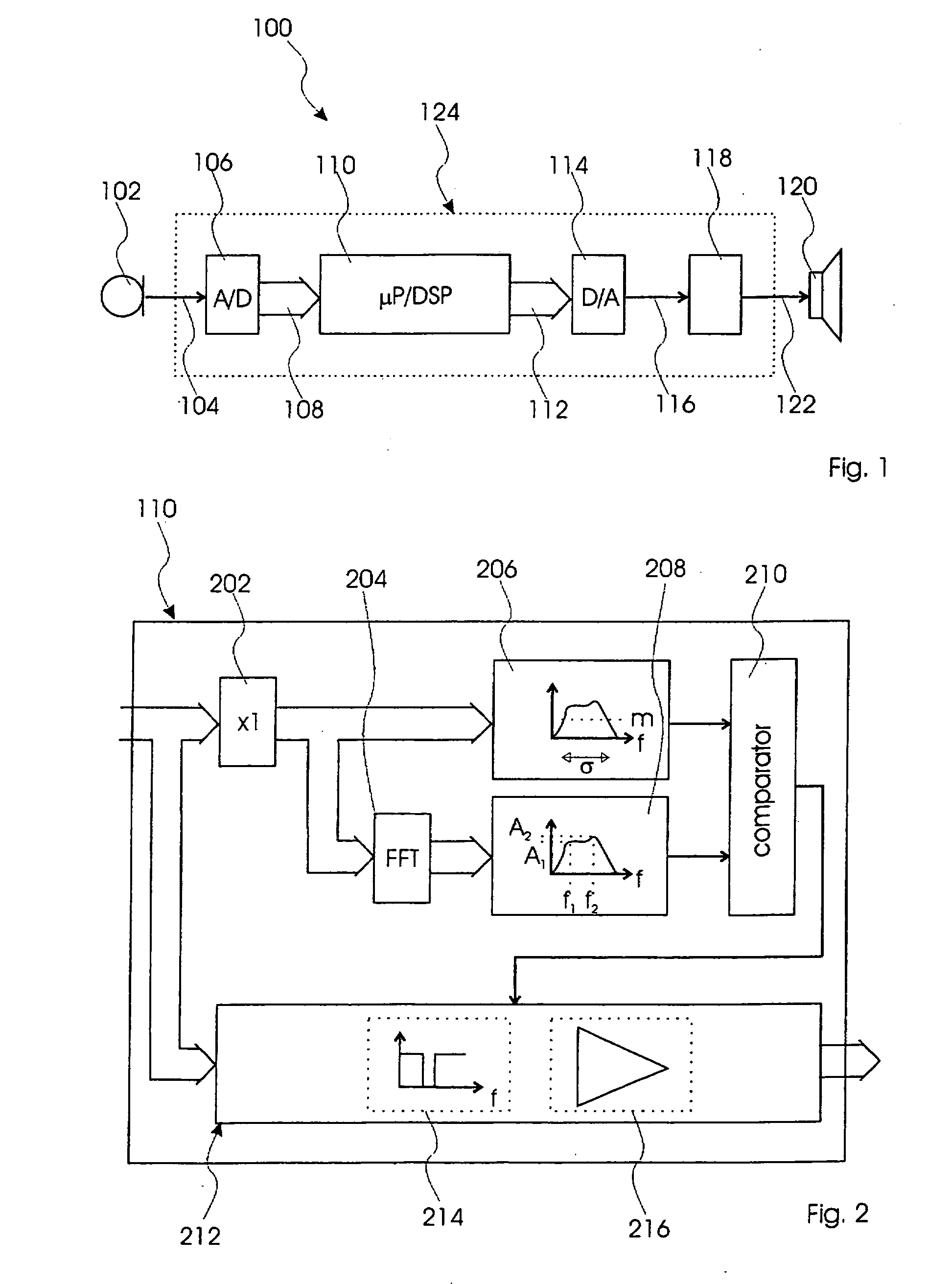
[0036]FIG. 1, shows a block diagram of a sound system according to the present invention and designated in entirety by reference numeral 100. The sound system 100 comprises a microphone unit 102 converting a sound to an analogue electrical sound signal. The analogue electrical sound signal is communicated through a first communication path 104 to an analogue-to-digital (A / D) converter 106, which converts the analogue electrical sound signal into a digital sound signal. The digital sound signal is communicated through a second communication path 108 to a sound processor 110, which processes the digital signal in accordance with a predetermined transfer function. The second communication path 108 may be a multi-channel bus. The sound processor 110 generates a processed digital signal and communicates this through a third communication path 112 to a digital-to-analogue (D / A) converter 114. The third communication path 112 may be identical to the second communication path 108 i.e. a con...

second embodiment

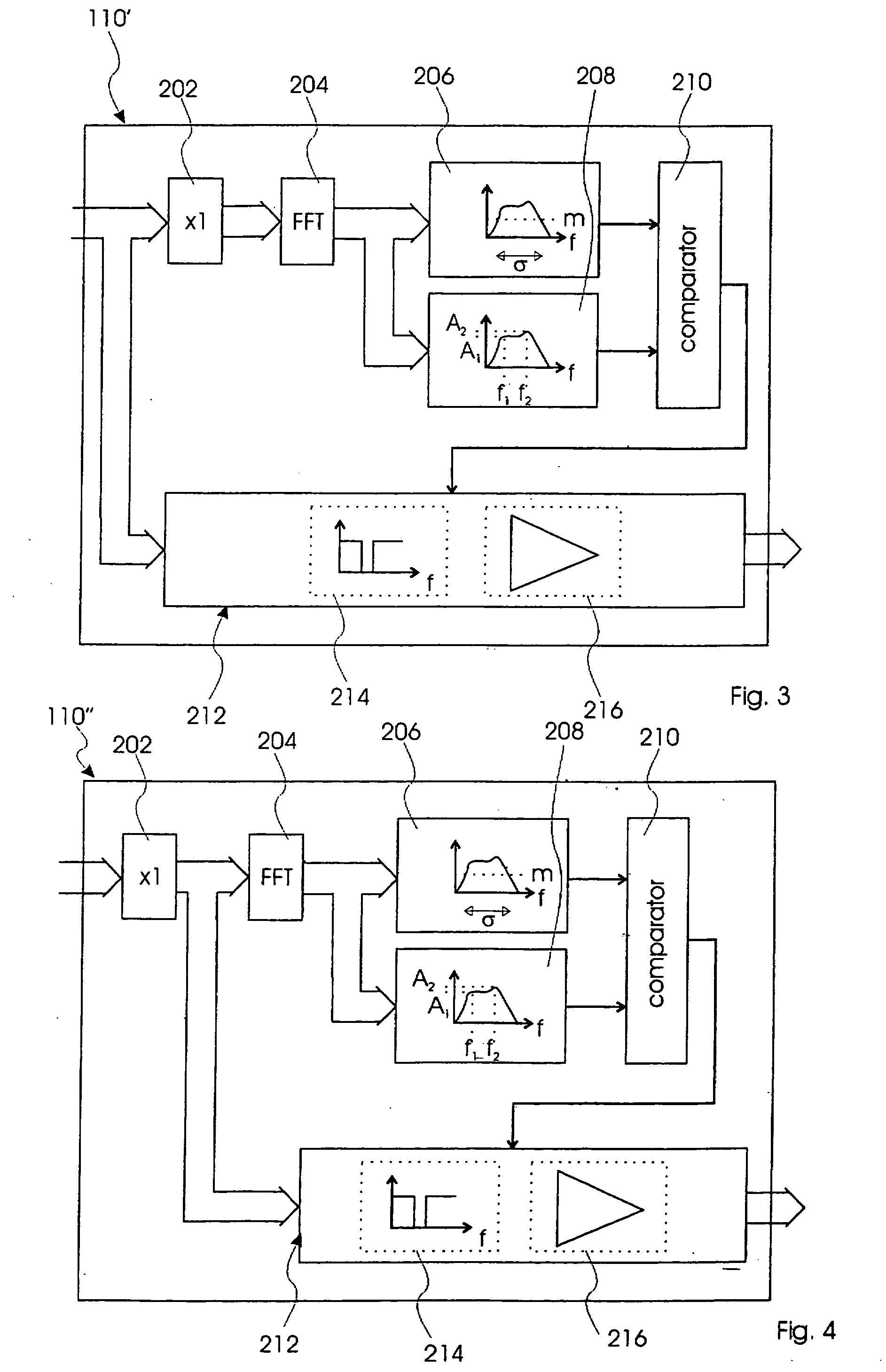
[0047]FIG. 3, shows a block diagram of a sound processor 110′ according to the present invention, which comprises the same elements of the sound processor 110 and these are referenced by the same numerals. The sound processor 110′ differs from the sound processor 110 by having the FFT unit 204 transforming the frames into frequency domain signals, which are then communicated to the threshold calculation unit 206 in this case being adapted to calculate a threshold value from the frame based on mean magnitude and standard deviation of the frequency spectrum of the frame.

[0048]FIG. 3, shows a block diagram of a sound processor 110″ according to a second embodiment of the present invention. The sound processor 110′ comprises the same elements of the sound processor 110 and 110′ and these are referenced by the same numerals. The sound processor 110″, however, differs from the sound processor 110′ by having the filter / amplifier unit 212 receive frames from the buffer unit 202 and thus per...

third embodiment

[0049]FIG. 4, shows a further block diagram of a sound processor 110′″ according to the present invention. The sound processor 110′″ comprises the same elements of the sound processors 110, 110′ and 110″ and these are referenced by the same numerals. The sound processor 110″, however, differs from the sound processors 110 and 110′ by having a filter / amplification unit 300 receiving the sound signal in the frequency domain from the FFT unit 204 and thus performing the filtering and amplifying operations on the sound signal in the frequency domain rather than on the digital sound signal or on the frames. The filter / amplification unit 300 further comprises an inverse FFT unit 302 for inverting the processed sound signal in the frequency domain back into a processed sound signal in the time domain.


PUM


Abstract

This invention relates to a sound system and method for processing acoustical sound. The sound system comprises a microphone for converting an acoustical sound to an electrical sound signal, a processor for processing the sound signal and for generating a processed sound signal, and a speaker for converting the processed sound signal to a processed acoustical sound. The processor comprises a calculating unit for calculating a threshold value based on mean magnitude and standard deviation of the sound signal, a FFT unit for transforming the sound signal into frequency domain, a peak identification unit for identifying a peak in the sound signal in frequency domain and for generating a peak signal, a comparator for comparing the threshold value with the peak signal and for generating a control signal identifying frequency of said peak, and a programmable notch-filter unit receiving said control signal and filtering out a bandwidth of the sound signal in accordance with the control signal thereby generating the processed sound signal.

Description

FIELD OF INVENTION [0001]This invention relates to a method and system for cancellation of acoustical feedback in a sound system, such as a public address sound system or a classroom sound system i.e. assistive learning system.BACKGROUND OF INVENTION [0002]American patent no.: U.S. Pat. No. 5,245,665 discloses a method and apparatus for eliminating acoustical feedback in a sound amplification system, wherein a sound is converted into a digital signal to be converted to a frequency spectrum by a Fast Fourier Transform (FFT) in a computer. Successive frequency spectrums are examined by the computer to determine the presence of an acoustic resonating feedback signal, and one or more filter devices are controlled by the computer for attenuating one or more narrow frequency bands of the amplified sound to eliminate undesirable acoustic feedback. The computer determines a maximum magnitude frequency which is then compared with the magnitude of one or more harmonics and / or sub-harmonics of...

Claims


Application Information

Patent Timeline
Patent Type & Authority Applications(United States)
IPC IPC(8): H04R3/00H03G5/00H03G9/00
CPCH03G5/005H04R3/02H03G5/22
Inventor SOMASUNDARAM, DEEPAK
Owner PHONIC EAR
Why Eureka
Try Eureka