

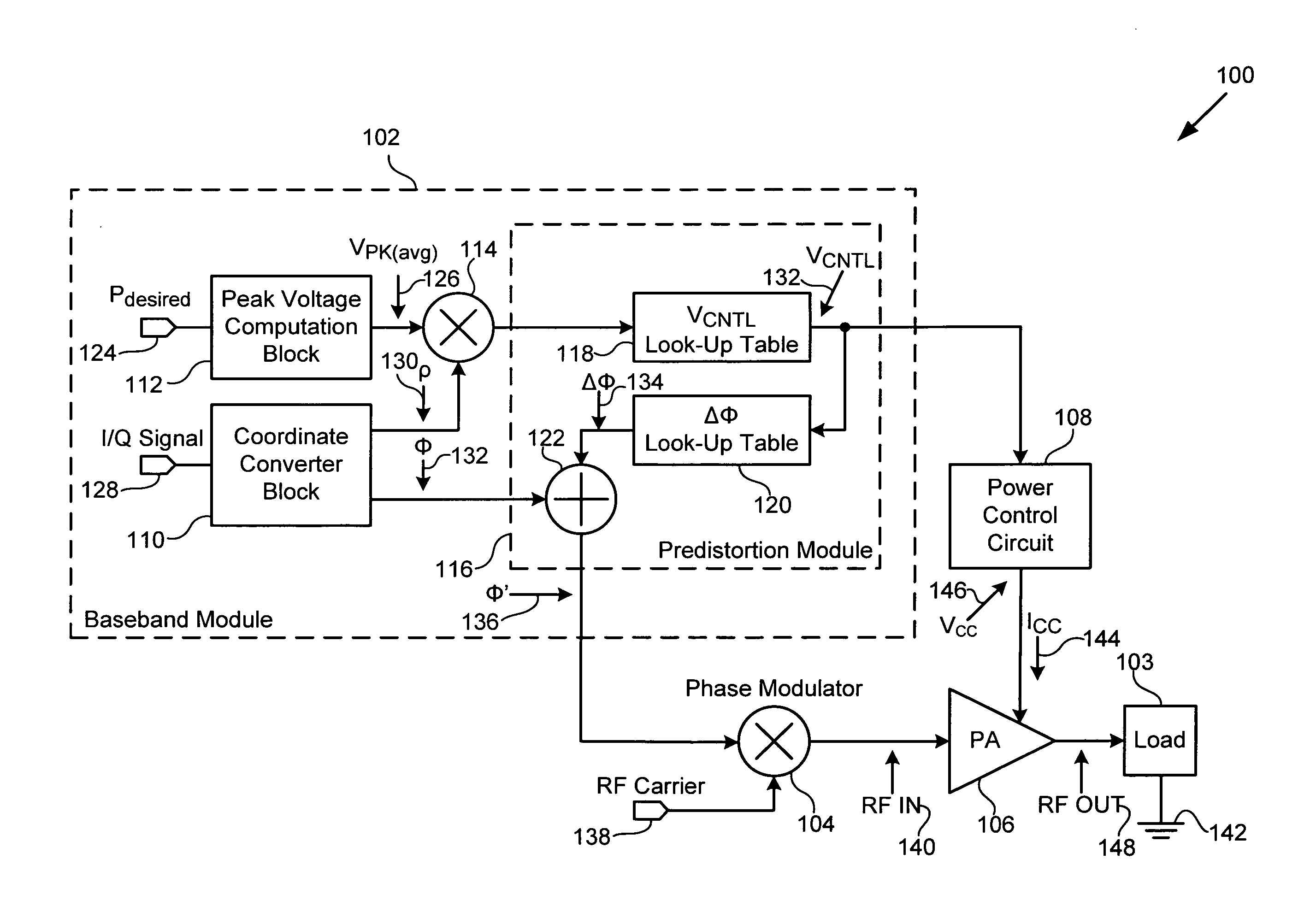
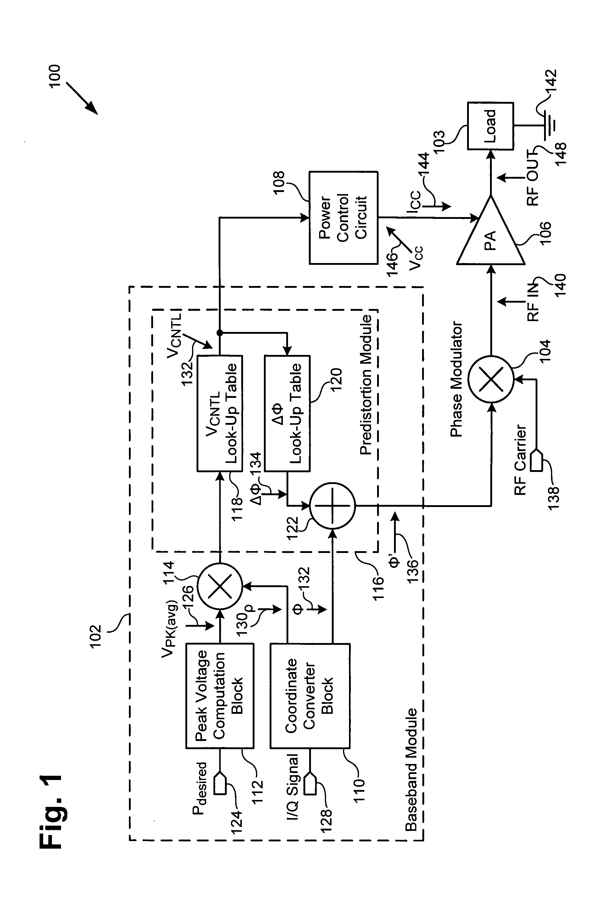
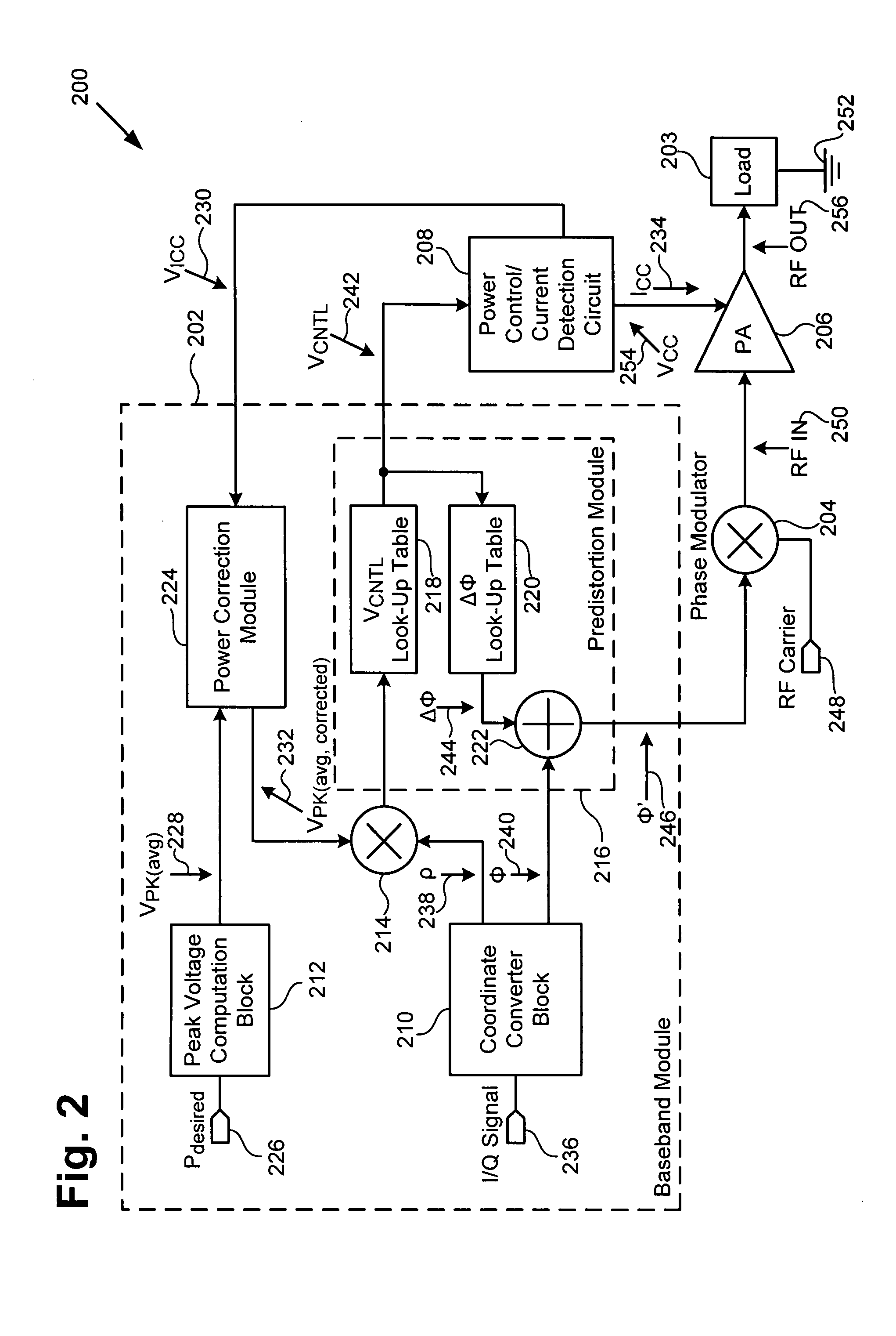
Output power correction module for amplifiers in transmitters
a technology of output power correction and transmitter, which is applied in the direction of rf amplifier, gain control, transmission, etc., can solve the problems of significant variations in power delivered to a varying load, and the conventional control of the output power of a power amplifier
- Summary
- Abstract
- Description
- Claims
- Application Information
AI Technical Summary
Benefits of technology
Problems solved by technology
Method used
Image

Examples
Embodiment Construction
[0013]The present invention is directed to an output power correction module for amplifiers in transmitters. The following description contains specific information pertaining to the implementation of the present invention. One skilled in the art will recognize that the present invention may be implemented in a manner different from that specifically discussed in the present application. Moreover, some of the specific details of the invention are not discussed in order not to obscure the invention. The specific details not described in the present application are within the knowledge of a person of ordinary skill in the art.
[0014]The drawings in the present application and their accompanying detailed description are directed to merely exemplary embodiments of the invention. To maintain brevity, other embodiments of the invention which use the principles of the present invention are not specifically described in the present application and are not specifically illustrated by the pres...
PUM
 Abstract
Description
Claims
Application Information