Fuell cell system and operation method of fuel cells

a fuel cell and fuel cell technology, applied in the field of fuel cell systems, can solve the problems of increasing the amount of steam, reducing the water content used for humidification, and unsatisfactory deterioration of the humidification performance of the humidifier, so as to enhance the humidification efficiency of the humidifier and increase the pressure of the exhaust gas

Inactive Publication Date: 2008-04-17
TOYOTA JIDOSHA KK
View PDF7 Cites 11 Cited by
  • Summary
  • Abstract
  • Description
  • Claims
  • Application Information

AI Technical Summary

Benefits of technology

[0021] The present invention is also directed to another fuel cell system including fuel cells that receive supplies of predetermined gases to generate electric power, as well as to a corresponding fuel cell operation method. This fuel cell system further includes: a humidifier that is provided in a flow path of an exhaust gas from the fuel cells and humidifies at least one of the predetermined gases supplied to the fuel cells with water content included in the exhaust gas discharged from the fuel cells; a decision module that identifies satisfaction or dissatisfaction of a condition for increasing an exhaust water content, which is included in the exhaust gas and is discharged downstream the humidifier, based on a state quantity of the exhaust gas; and a pressure increase module that, upon satisfaction of the condition for increasing the exhaust water content, increases pressure of the exhaust gas in the humidifier to enhance a humidification efficiency of the humidifier.

Problems solved by technology

This prior art technique, however, does not take into account the exhaust gas discharged outside of the fuel cells and may thus cause undesirable deterioration of the humidification performance of the humidifier according to the quantity of the exhaust gas discharged outside.
In such circumstances, an increase in amount of steam may only raise the water content discharged outside as the exhaust gas.
This may decrease the water content used for humidification and lower the humidification performance of the humidifier.

Method used


Image

  • Fuell cell system and operation method of fuel cells
  • Fuell cell system and operation method of fuel cells
  • Fuell cell system and operation method of fuel cells

Examples


first embodiment

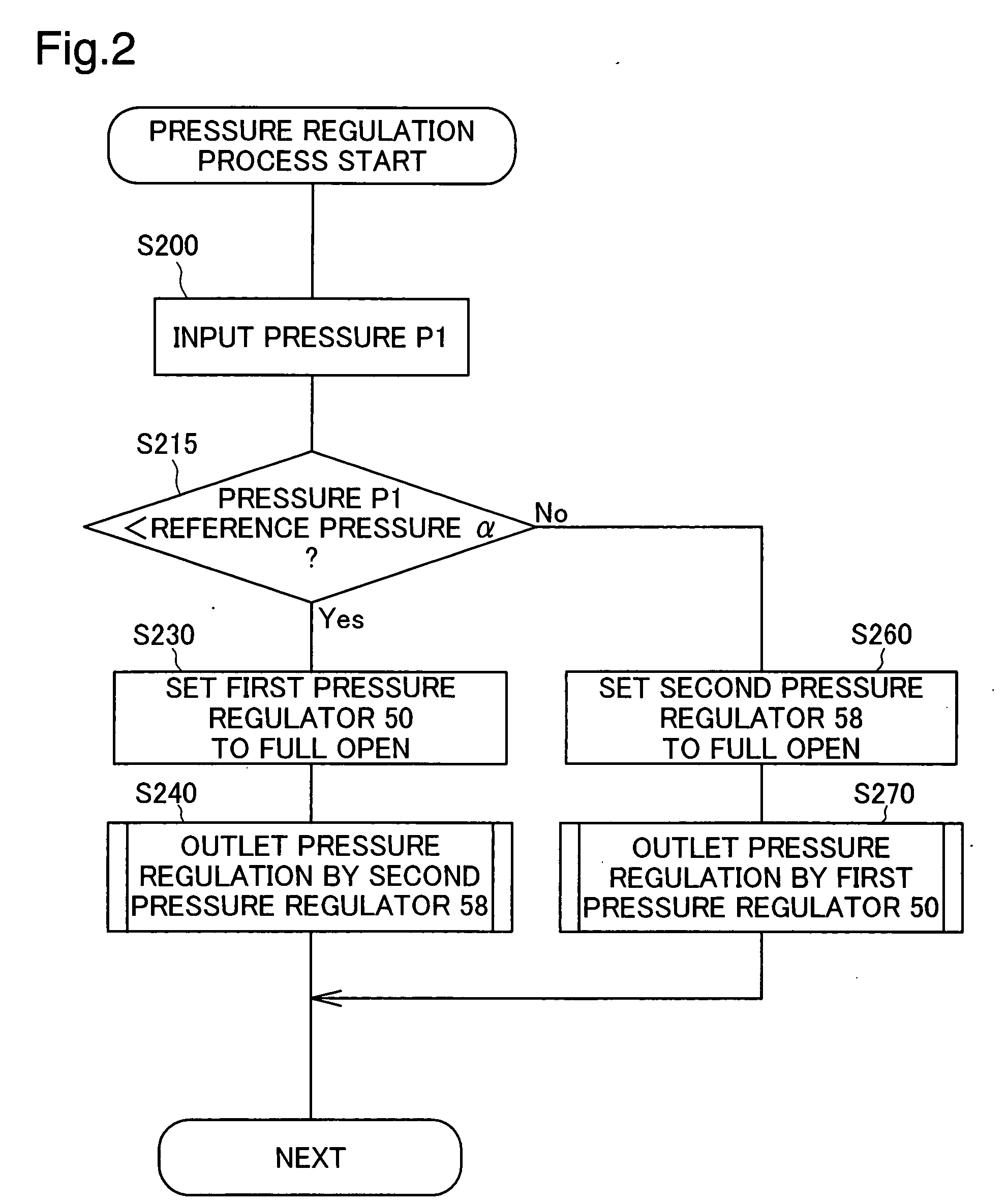
[0028] B. Pressure Regulation Process in First Embodiment

second embodiment

[0029] C. Pressure Regulation Process in Second Embodiment

[0030] D. Modifications

A. General Configuration of Fuel Cell System

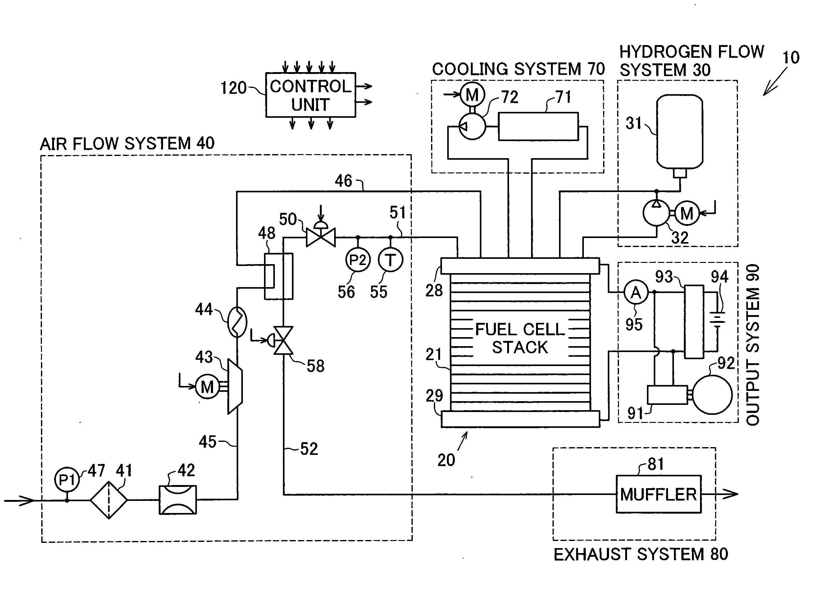
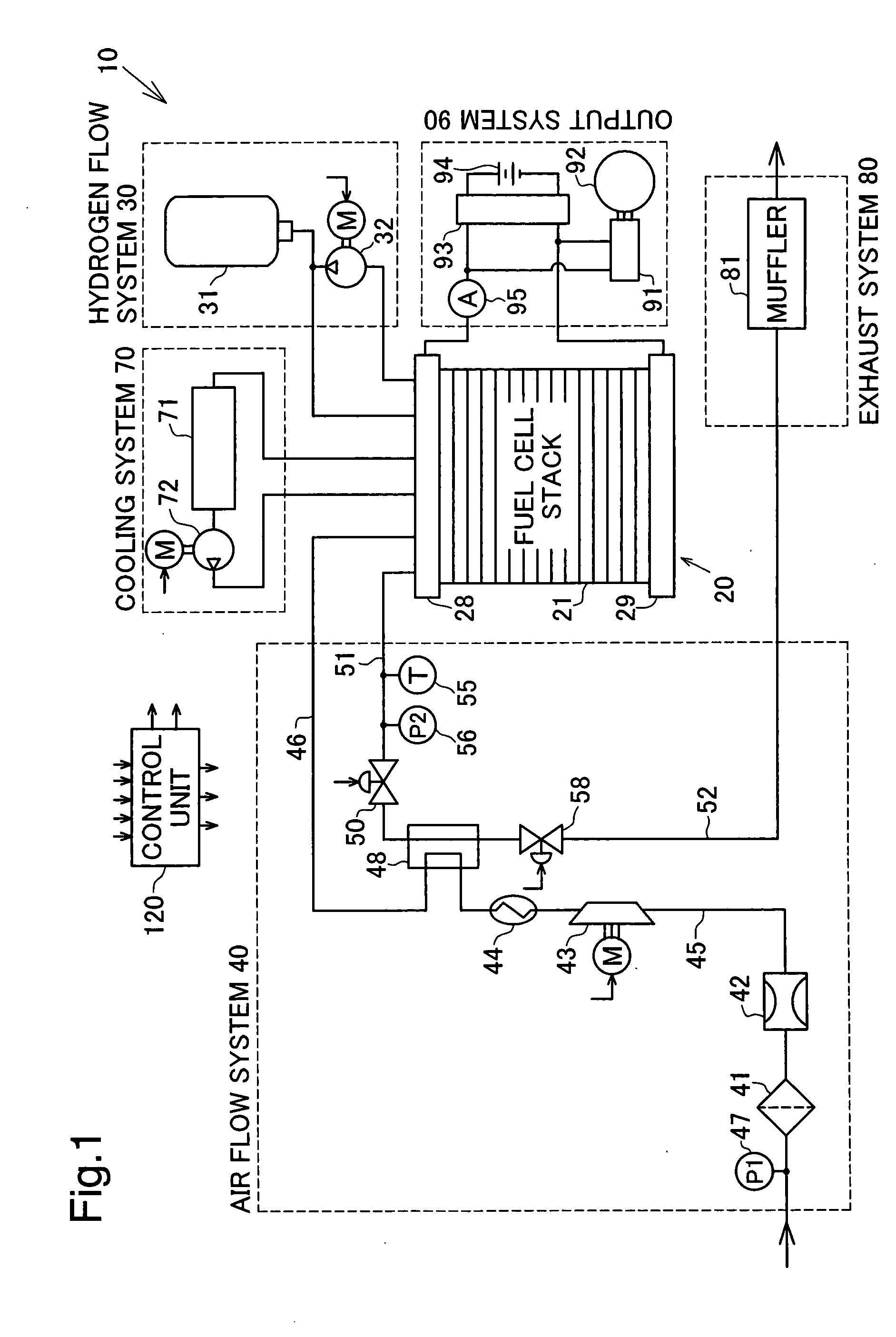
[0031]FIG. 1 schematically illustrates the configuration of a fuel cell system 10 embodying the invention. The fuel cell system 10 includes a stack of fuel cells or fuel cell stack 20 that receives supplies of hydrogen gas and the air as reactive gases and generates electric power through an electrochemical reaction of hydrogen with oxygen included in the air. The fuel cell system 10 is mounted on a vehicle (not shown) to work as a driving source for driving the vehicle with the electric power generated by the fuel cell stack 20. As illustrated, the fuel cell system 10 includes a hydrogen flow system 30 to feed the hydrogen gas to the fuel cell stack 20, an air flow system 40 to feed the air to the fuel cell stack 20, and a control unit 120 to control the constituents of the fuel cell system 10, in addition to the fuel cell stack 20.

[0032] The fuel cell st...


PUM


Abstract

A fuel cell system of the invention includes: fuel cells that receive supplies of predetermined gases to generate electric power; and a humidifier that humidifies at least one of the predetermined gases supplied to the fuel cells with water content included in the exhaust gas discharged from the fuel cells. The fuel cell system further has: an exhaust water content detection module that detects an exhaust water content, which is included in the exhaust gas and is discharged downstream the humidifier; and a regulation module that, in response to detection of the exhaust water content of not lower than a preset level, restricts the exhaust water content discharged downstream the humidifier. This technique of the invention ensures adequate humidification control.

Description

TECHNICAL FIELD [0001] The present invention relates to a fuel cell system including fuel cells that receive supplies of predetermined gases to generate electric power. More specifically the invention pertains to humidification control with the water content included in an exhaust gas from the fuel cells. BACKGROUND ART [0002] In a fuel cell system that receives supplies of hydrogen gas and the air as reactive gases and generates electric power through an electrochemical reaction of hydrogen with oxygen included in the air, humidification of the air supplied to the fuel cells is required to ensure sufficiently high power generation efficiency. One proposed technique applied to the fuel cell system uses a humidifier to humidify the air supplied to the fuel cells with the water content included in an exhaust gas produced on an oxygen electrode by the electrochemical reaction (see, for example, JP-A-2002-75418). [0003] The fuel cell system disclosed in the cited patent document causes ...

Claims


Application Information

Patent Timeline
Patent Type & Authority Applications(United States)
IPC IPC(8): F24F11/00
CPCH01M8/04007H01M8/04082H01M8/04141H01M8/0435H01M8/0441Y02T90/32H01M8/04761H01M2008/1095H01M2250/20Y02E60/50H01M8/04522Y02T90/40
Inventor DAISUKE, YAMAZAKI
Owner TOYOTA JIDOSHA KK
Why Eureka
Try Eureka