Holding apparatus and method for manufacturing honeycomb structure

a technology of holding apparatus and honeycomb, which is applied in the direction of manufacturing tools, applications, transportation and packaging, etc., can solve the problems of harmful to the environment and the human body, soot, and particles in exhaust gases discharged from vehicles, such as buses and trucks, to become serious problems, and achieve the effect of reducing the number of accidents

Active Publication Date: 2008-04-17
IBIDEN CO LTD
View PDF99 Cites 108 Cited by
  • Summary
  • Abstract
  • Description
  • Claims
  • Application Information

AI Technical Summary

Benefits of technology

[0017] The holding apparatus of the present invention includes a first holding unit including at least two supporting rollers rotatable around rotation shafts which extend substantially parallel with each other; a second holding unit including at least one supporting roller rotatable around a rotation shaft; and at least one holding mechanism having the above-mentioned first holding unit and the above-mentioned second holding unit. The rotation shafts of the su

Problems solved by technology

In recent years, particulates, such as soot, contained in exhaust gases discharged from internal combustion engines of vehicles, such as buses and trucks, construction machines and the like, have become serious problems as contaminants harmful to the environment and the human body.
Moreover, even in the case where the falling in the middle of the transportation is avoided, since the honeycomb structure is held in the tilted orientation, a corner portion or the like located near the border between an end face and a side face of the honeycomb structure is first brought into contact with a mount face, upon placing it at a predetermined position after the transporting process, to cause chippings and cracks on the corner portion or the like.
In the above-menti

Method used


Image

  • Holding apparatus and method for manufacturing honeycomb structure
  • Holding apparatus and method for manufacturing honeycomb structure
  • Holding apparatus and method for manufacturing honeycomb structure

Examples


example 1

[0243] 250 kg of an α-type silicon carbide powder having an average particle diameter of 10 μm, 100 kg of an α-type silicon carbide powder having an average particle diameter of 0.5 μm and 20 kg of an organic binder (methyl cellulose) were mixed to prepare a powder mixture.

[0244] Next, separately, 12 kg of a lubricant (UNILUB, manufactured by NOF Corp.), 5 kg of a plasticizer (glycerin) and 65 kg of water were mixed to prepare a liquid mixture, and this liquid mixture and the powder mixture were mixed by using a wet mixing machine so that a wet mixture was prepared.

[0245] Next, this wet mixture was transported to an extrusion-molding machine by using a transporting apparatus, and carried into a material carrying port of the extrusion-molding machine.

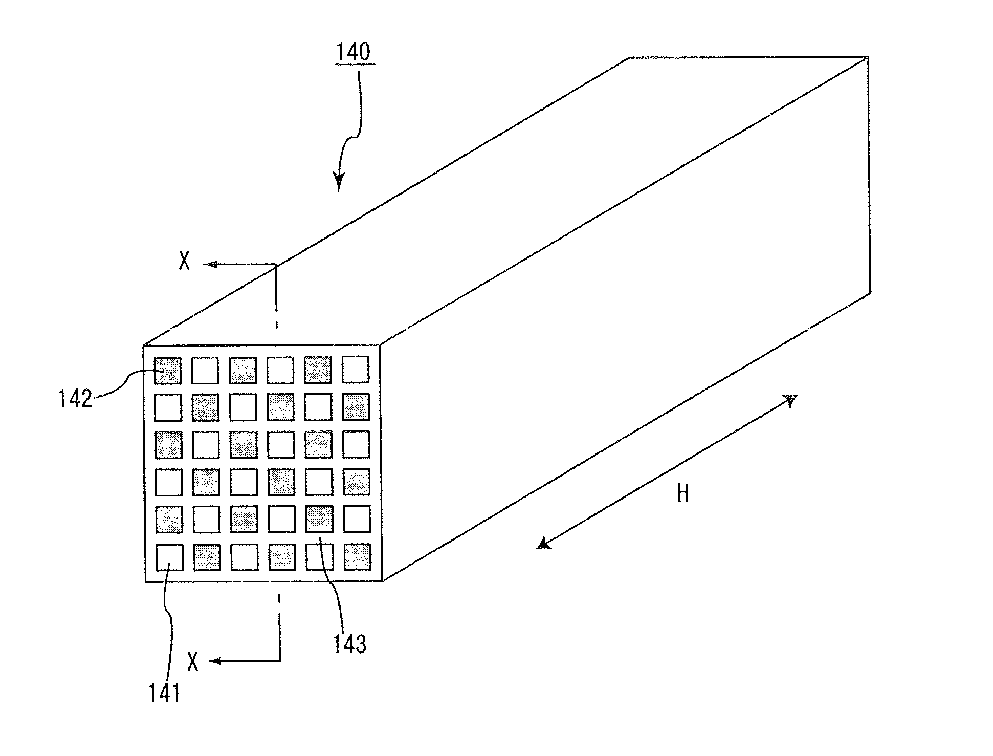
[0246] Thus, a molded body that has not been sealed having a shape as shown in FIG. 12(a) was manufactured through an extrusion-molding process.

[0247] Next, after the above-mentioned molded body had been dried by using a microwave dr...


PUM

PropertyMeasurementUnit
Electrical resistanceaaaaaaaaaa
Shapeaaaaaaaaaa
Distanceaaaaaaaaaa

Abstract

A holding apparatus includes a first holding unit including at least two supporting rollers rotatable around rotation shafts which extend substantially parallel with each other; a second holding unit including at least one supporting roller rotatable around a rotation shaft; and at least one holding mechanism having the first holding unit and the second holding unit. The rotation shafts of the supporting rollers of the first holding unit and the rotation shaft of the supporting roller of the second holding unit are substantially in parallel with each other. By moving at least one of the first holding unit and the second holding unit, an object to be held is held between the first holding unit and the second holding unit by using the supporting rollers.

Description

CROSS-REFERENCE TO RELATED APPLICATIONS [0001] This application is a continuation application of PCT / JP2006 / 310922 filed on May 31, 2006, entitled “HOLDING APPARATUS AND METHOD FOR MANUFACTURING HONEYCOMB STRUCTURE.” The contents of this application are incorporated herein by reference in its entirety.BACKGROUND OF THE INVENTION [0002] 1. Field of the Invention [0003] The present invention relates to a holding apparatus and a method for manufacturing a honeycomb structure. [0004] 2. Discussion of the Background [0005] In recent years, particulates, such as soot, contained in exhaust gases discharged from internal combustion engines of vehicles, such as buses and trucks, construction machines and the like, have become serious problems as contaminants harmful to the environment and the human body. [0006] For this reason, various honeycomb filters, which use honeycomb structures including porous ceramic materials, have been proposed as filters that capture particulates in exhaust gases...

Claims


Application Information

Patent Timeline
IPC IPC(8): B23Q3/00B28B1/00
CPCB28B13/04B28B17/00Y10T29/49998Y10T29/49345B65G47/90
Inventor KOBAYASHI, HIROYUKI
Owner IBIDEN CO LTD
Why Eureka
Try Eureka