Sheet feeding device and image forming apparatus

a feeding device and a technology for forming apparatus, applied in the direction of transportation and packaging, thin material processing, article separation, etc., can solve the problems of slow feeding of sheets, jamming, and the inability of the conventional feeding device to determine whether or not a second and subsequent sheet is loosened, and achieves the effect of stable loosening condition and inexpensive structur

Inactive Publication Date: 2008-04-17
CANON KK
View PDF14 Cites 13 Cited by
  • Summary
  • Abstract
  • Description
  • Claims
  • Application Information

AI Technical Summary

Benefits of technology

[0019]Accordingly, the present invention has accomplished in views of such a situation and an object of the invention is to provide a sheet feeding device and image forming apparatus capable of stabilizing loosening condition with an inexpensive structure.

Problems solved by technology

However, the conventional sheet feeding device cannot determine whether or not a second and following sheets are loosened (in a floating condition) because the paper face upper limit detection sensor 123 can detect only the top face position of the topmost sheet.
In this case, sheet feeding failure occurs, so that jamming is generated.
If it takes time for the tray 101 to be lifted up, feeding of the sheet becomes slow thereby lowering productivity.
Further, if the next sheet delays, it is detected that the sheets are not conveyed at an appropriate interval by a sensor or the like, and consequently, the sensor determines that it is jamming by mistake.
Therefore, loosening condition of the sheets cannot be determined.
However, in this case, the device is complicated and cost is increased.

Method used


Image

  • Sheet feeding device and image forming apparatus
  • Sheet feeding device and image forming apparatus
  • Sheet feeding device and image forming apparatus

Examples


Embodiment Construction

[0036]Hereinafter the preferred embodiments of the present invention will be described in detail with reference to the accompanying drawings.

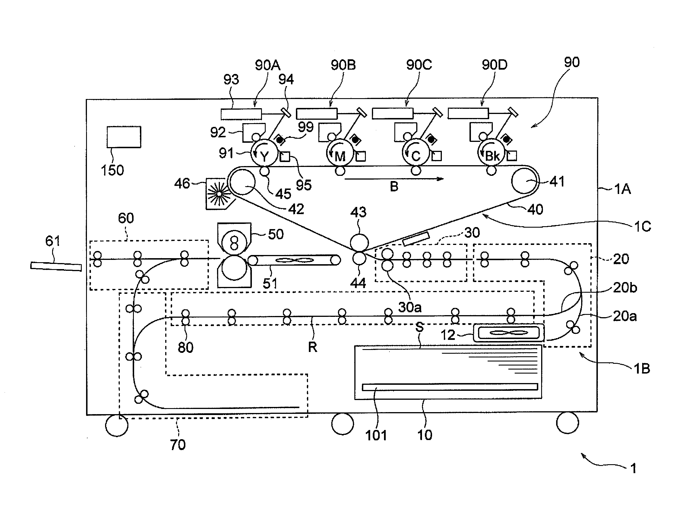
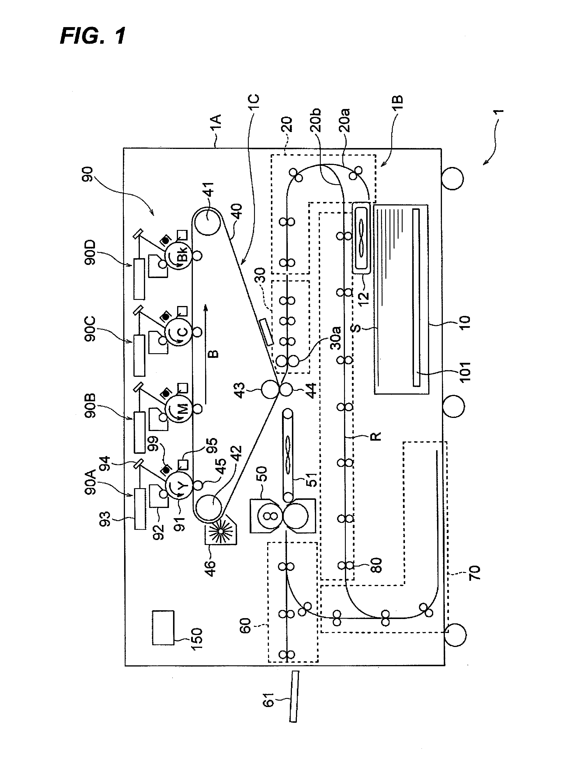
[0037]FIG. 1 is a diagram showing a schematic structure of a color image forming apparatus which is an example of the image forming apparatus equipped with the sheet feeding device according to the first embodiment of the present invention.

[0038]In FIG. 1, a color image forming apparatus 1, and a color image forming apparatus main body 1A (hereinafter referred to as apparatus main body) are shown. The apparatus main body 1A includes an image forming portion 90, a sheet feeding device 1B for conveying a sheet S and a transfer portion 1C for transferring a toner image formed by the image forming portion 90 to the sheet S conveyed by the sheet feeding device 1B.

[0039]The image forming portion 90 includes image forming units 90A-90D for yellow (Y), magenta (M), cyan (C) and black (Bk). Each of these image forming units 90A-90D includes a photosensi...


PUM


Abstract

An upper limit detection sensor detects that a top face position of a sheet stack on a tray reaches an upper limit position which enables feeding of sheets one by one by a sheet feeding portion and a lower limit detection sensor detects that the top face position of the sheet stack on the tray reaches a lower limit position which enable feeding of sheets one by one. When the sheet stack is loosened by blowing air against a side face of the sheet stack on the tray with an air spouting nozzle provided on an air loosening device, if a sheet floated by air from the air loosening device exceeds an upper limit position of a feeding enabled range, the lowering amount of the tray is controlled so that at least a sheet next to the sheet to be fed is not lower than a lower end position of the air spouting port of the air loosening device.

Description

BACKGROUND OF THE INVENTION[0001]1. Field of the Invention[0002]The present invention relates to a sheet feeding device and an image forming apparatus and more specifically to a device for loosening a sheet stack with air before each sheet is fed.[0003]2. Description of the Related Art[0004]Conventionally, an image forming apparatus such as a copying machine, electrophotographic printer, ink jet printer, facsimile, a printing machine is equipped with a sheet feeding device for feeding the sheets one by one from a storage portion in which a plurality of the sheets are stored.[0005]As such a sheet feeding device, recently, there has been proposed a sheet feeding device using air suction method of conveying a sheet by sucking the sheet loaded on a tray, this sheet feeding device using air suction force and conveying force of an endless belt. This technology has been described in Japanese Patent Application Laid-Open (JP-A) Nos. 07-89625 and 2005-104723. In the meantime, such a sheet fe...

Claims


Application Information

Patent Timeline
Patent Type & Authority Applications(United States)
IPC IPC(8): B65H5/22
CPCB65H1/14B65H3/128B65H3/48B65H7/02B65H2511/22B65H2511/51B65H2801/06B65H2553/612B65H2220/02B65H2220/01B65H2553/61
Inventor FUJITA, TAKASHI
Owner CANON KK
Why Eureka
Try Eureka