Wheel balancing device

a balancing device and wheel technology, applied in the direction of spoked wheels, mechanical equipment, transportation and packaging, etc., can solve the problems of increasing the number of parts and the manufacturing cost of the balancing device, the difficulty of compressing and flattening a protruding protruding to result in a rivet, and the imbalance of the wheel rotating, so as to achieve easy color decoration, reduce the cost, and facilitate the effect of forming

Inactive Publication Date: 2008-04-17
P C PRODS INT
View PDF5 Cites 4 Cited by
  • Summary
  • Abstract
  • Description
  • Claims
  • Application Information

AI Technical Summary

Benefits of technology

[0012]The wheel balancing device of this invention is preferably made of iron metal or iron-based metal or other material substitute of using lead thereby meet the standpoint of environmental protection. Further, because the wheel balancing body and the engaging part are coupled together by enwrapping such two parts with plastic or plastic-contained composition, forming is easier and lower in cost, also can prevent rust caused by outer moisture and being easily to perform color decoration.

Problems solved by technology

In an automobile wheel assembly including a wheel and a tire, a dynamic imbalance may exist when the wheel is rotated.
However, since the material containing the lead has a problem in an influence to a natural environment, the wheel balancing device has the body made of an iron, iron alloy or other materials being friendly with the environment has been developed.
The balancing device according to Japanese U.M. No. 3046046 has an disadvantage that the numbers of parts and a manufacturing cost of the balancing device increase, since the engaging member is fixed to the weight body by riveting.
Moreover, in case that the weight body is constructed from a hard material such as an iron, compressing and flattening a protrusion to result in a rivet is relatively difficult.
On the other hand, the wheel balancing device disclosed in aforesaid US patent Publication has some defects leaved that the clip is coupled to the underside of the weight body, if there are some defects while caulking the cast-iron which will often causing crack in the metallic ground-boundary and causing broken afterward, sometimes even the clip is hammered to the rim of the wheel, but the weight body will be loosed freely.
Also, the manufacturing cost of the weight body increases due to the protruded pillar formed within the groove.

Method used


Image

  • Wheel balancing device
  • Wheel balancing device
  • Wheel balancing device

Examples


Embodiment Construction

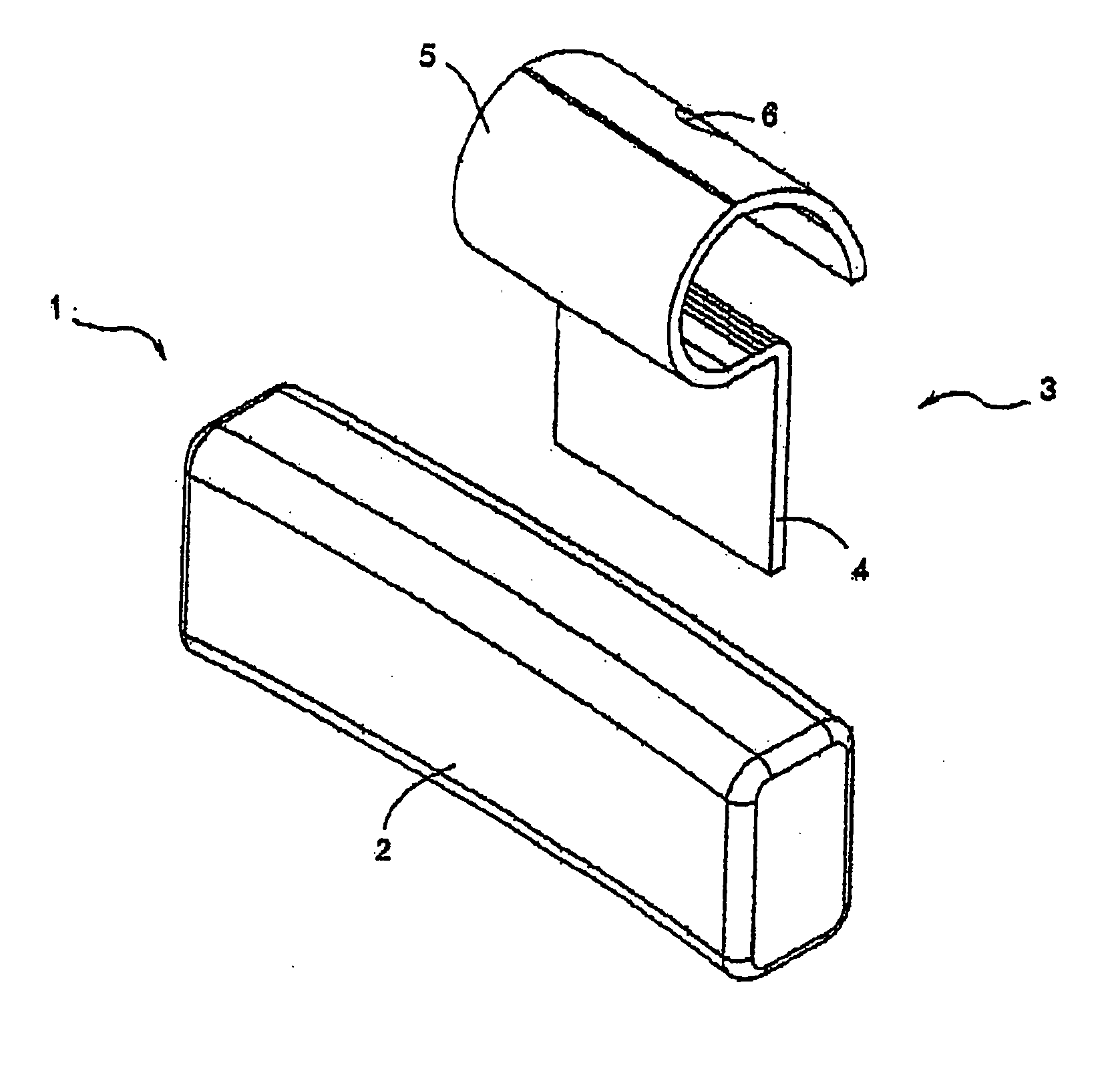
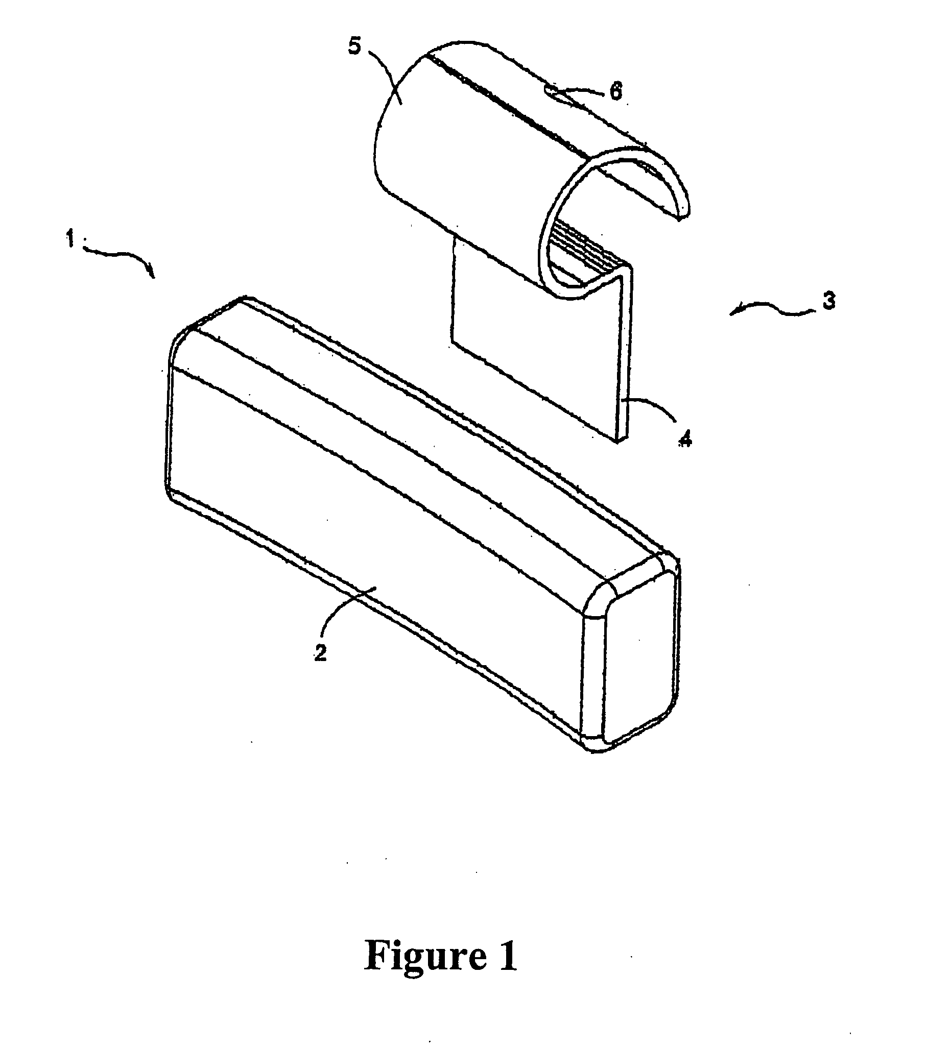
[0022]According to FIG. 1, it shows a wheel balancing device comprising a wheel balancing body 1 and an engaging part 3. The wheel balancing body 1 composes of a wheel rim engaging bar 2 made of iron metal or iron-based metal component which is formed in various shape with appropriate weight as required, for instance 5 grams or 10 grams etc.

[0023]The engaging part 3 comprises an engaging plate 4 having one end being provided for engaging and fixing to one end of the wheel rim engaging bar 2 of the wheel balancing body 1 and the other end is bent into the form of an upper curve 5, in which the said curve can be locked and fixed to a wheel rim of an automobile (as shown in FIG. 6). The engaging part 3 may be provided, on the upper curve 5, with a number of punched holes 6 to fasten and support the engaging member inserted thereto (not shown in Fig.).

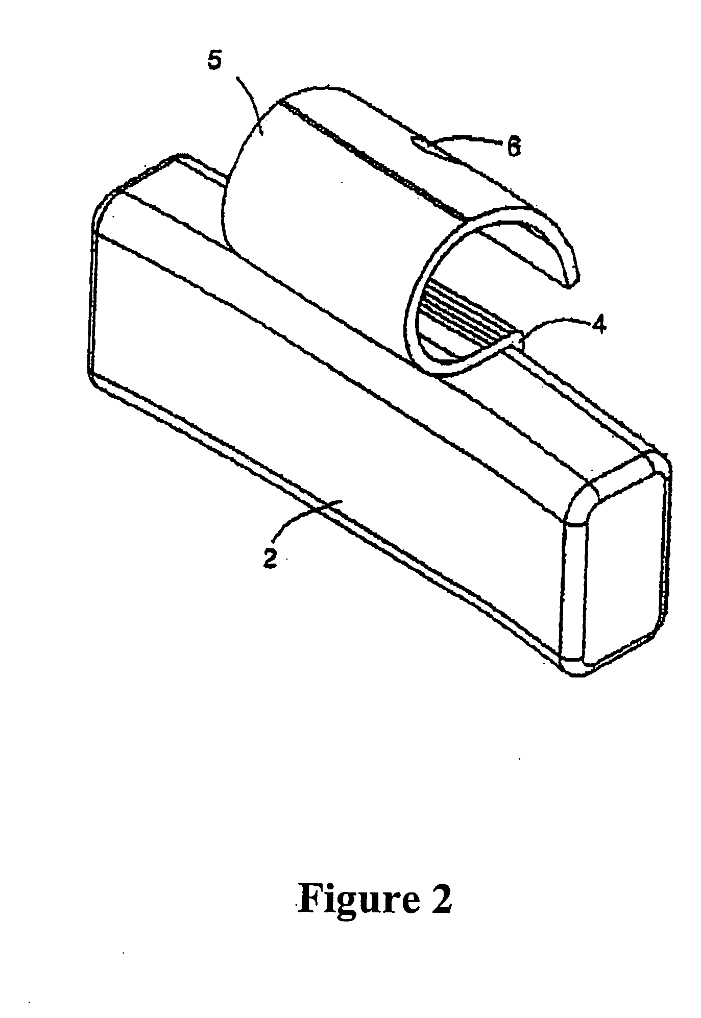
[0024]According to FIG. 2, the engaging part 3 is mounted to the wheel balancing body 1 wherein one end of the engaging plate 4 is overla...


PUM


Abstract

A wheel balancing device of this invention comprising a wheel balancing body having a wheel rim engaging bar made of iron metal or iron-based metal component to be formed in any shape as required. Being provided on one side of the wheel balancing body is an engaging part fixed thereto. The engaging part is composed of an engaging plate having one end engaged and fixed to one end of the wheel rim engaging bar by a locking means and the other end is bent as an upper curve to be locked and fixed to a wheel rim of an automobile. The wheel rim engaging bar and a part of engaging plate are enwrapped by the outer cover plate made of plastic or plastic-contained composition.

Description

FIELD OF THE INVENTION[0001]The present invention relates to a wheel balancing device, especially a wheel balancing device for an automobile.BACKGROUND OF THE INVENTION[0002]In an automobile wheel assembly including a wheel and a tire, a dynamic imbalance may exist when the wheel is rotated. Generally, to compensate for this imbalance, the wheel is provided with a wheel balancing device.[0003]As shown in FIGS. 7 and 8, a conventional wheel balancing device comprising a wheel balancing body 11 made of lead in various form of size and weight as provided such as 5 grams or 10 grams. A clip including an locking plate 12 having one end being embedded in the wheel balancing body 11 thereby define a wheel balancing device and the other end of the plate 12 being rolled as a curve in upper part 13 which is a long flat plate and some curve part for locking and fixing to a wheel rim of a tire. On the top of the said upper part curve 13 may provided with a number of punched holes 14 to be faste...

Claims


Application Information

Patent Timeline
Patent Type & Authority Applications(United States)
IPC IPC(8): B60B19/00
CPCF16F15/324
Inventor CHANCHAREON, PRAVUTH
Owner P C PRODS INT
Why Eureka
Try Eureka