Mounting film for liquid crystal display drive chip and method for manufacturing the same

Active Publication Date: 2008-04-17
INFOVISION OPTOELECTRONICS HLDG LTD
View PDF2 Cites 22 Cited by
  • Summary
  • Abstract
  • Description
  • Claims
  • Application Information

AI Technical Summary

Benefits of technology

[0047]According to the present invention, the same COF mounting film for liquid crystal display drive chip may be generally used in case that the distance between the liquid crystal display panel and the control circu

Problems solved by technology

However, in such a situation, the manufacturing cost will increase markedly due to preparation of various COF mounting films for liquid cryst

Method used


Image

  • Mounting film for liquid crystal display drive chip and method for manufacturing the same
  • Mounting film for liquid crystal display drive chip and method for manufacturing the same
  • Mounting film for liquid crystal display drive chip and method for manufacturing the same

Examples


Example

REFERENCE NUMERALS

[0058]102—liquid crystal display panel; 103—control circuit substrate; 104—hole at the tip of the slit; 105—slit; 106—drive chip; 112—COF mounting film for a liquid crystal display drive chip; 121—line that is substantially parallel to the engaging side of the liquid crystal display panel with the COF mounting films for drive chips; W11, W12 and W13—distance between the control circuit substrate and the liquid crystal display panel at different positions.

DETAILED DESCRIPTION OF THE INVENTION

[0059]Embodiments of the present invention will be described hereinafter with reference to accompany drawings.

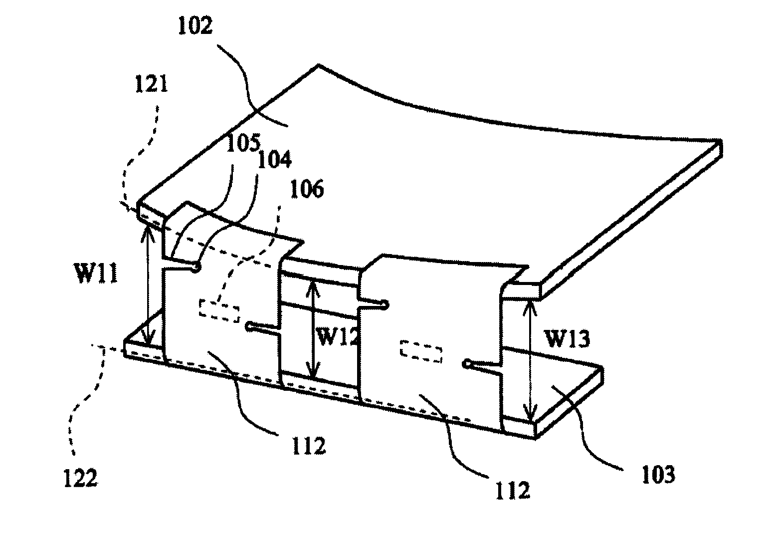
[0060]FIG. 1 is a perspective view which illustratively shows COF mounting films for liquid crystal display drive chips according to one embodiment of the present invention and the arrangement thereof.

[0061]In FIG. 1, a reference numeral 103 refers to a control circuit substrate, 102 refers to a liquid crystal display panel, 112 refers to a COF mounting film for a liquid...


PUM


Abstract

The present invention provides a mounting film for a liquid crystal display drive chip and a method for manufacturing the same. The mounting film is provided with a slit cut from a side edge thereof, or provided with a weakened line for forming the slit. When a distance between a liquid crystal display panel and a control circuit substrate of the liquid crystal display unit is un-uniform, the opening degree of the slit is variable accordingly to accommodate variations in the distance. Such a COF mounting film for a liquid crystal display drive chip may be generally used even though a distance between the liquid crystal display panel and the control circuit substrate varies slightly. Therefore, the manufacturing cost of the liquid crystal display unit may be reduced.

Description

CROSS-REFERENCES TO RELATED APPLICATIONS[0001]This application claims the benefit of Japanese Patent Application No. 2006-281036 filed on Oct. 16, 2006.FIELD OF THE INVENTION[0002]The present invention relates to a manufacturing technology for electronic display unit. More particularly, the present invention relates to a mounting film for a liquid crystal display drive chip and a method for manufacturing the same.BACKGROUND OF THE INVENTION[0003]Recently, drive circuits for driving liquid crystal cells in form of semiconductor chips are mounted on films. Conventionally, the film equipped with the semiconductor chip (COF, chip on film, also referred to as “COF mounting film for a liquid crystal display drive chip” hereinafter) is arranged between a liquid crystal display panel and a control circuit substrate.[0004]FIG. 10 schematically shows that COF mounting films for liquid crystal display drive chips are provided between a liquid crystal display panel and a control circuit substra...

Claims


Application Information

Patent Timeline
IPC IPC(8): G02F1/1333G02F1/13
CPCG02F1/13452H05K2201/09063H05K1/148H05K1/028H05K2201/10681
Inventor KOHNO, AKIFUMI
Owner INFOVISION OPTOELECTRONICS HLDG LTD
Why Eureka
Try Eureka