Apparatus for determining a physical quantity

a technology for physical quantities and apparatus, applied in the field of apparatus for determining the physical quantity of samples, can solve the problems of difficult control, therefore evaluation, and difficulty in determining quality, and achieve the effects of simple and clear determination of sample quality, high accuracy, and easy identification

Inactive Publication Date: 2008-04-17
LABOR FUER MESSTECHN DR HANS STABINGER
View PDF7 Cites 6 Cited by
  • Summary
  • Abstract
  • Description
  • Claims
  • Application Information

AI Technical Summary

Benefits of technology

[0034]According to another feature of the present invention, the image can be compared with a reference image, in particular an image of the empty test tube. Such method can enable a particularly simple and clear determination of the sample quality and can also be performed by an observer not specially trained for this task. A partial or complete automation of this process is also feasible, wherein an electronic, for example computerized, evaluation system compares an image of the sample with a reference image, whereby differences are automatically determined by the evaluation system or such differences are processed for a subsequent, better identification of differences by the observer. Contamination of the test tube can also be easily identified before the tube is filled through comparison with at reference image of an empty test tube.
[0035]According to another feature of the present invention, the im

Problems solved by technology

Determining the quality is frequently quite difficult and the quality of the measurement often depends on an estimate from the tester.
However, this is generally not the case when a physical quantity of a sample is determined

Method used


Image

  • Apparatus for determining a physical quantity
  • Apparatus for determining a physical quantity
  • Apparatus for determining a physical quantity

Examples


first embodiment

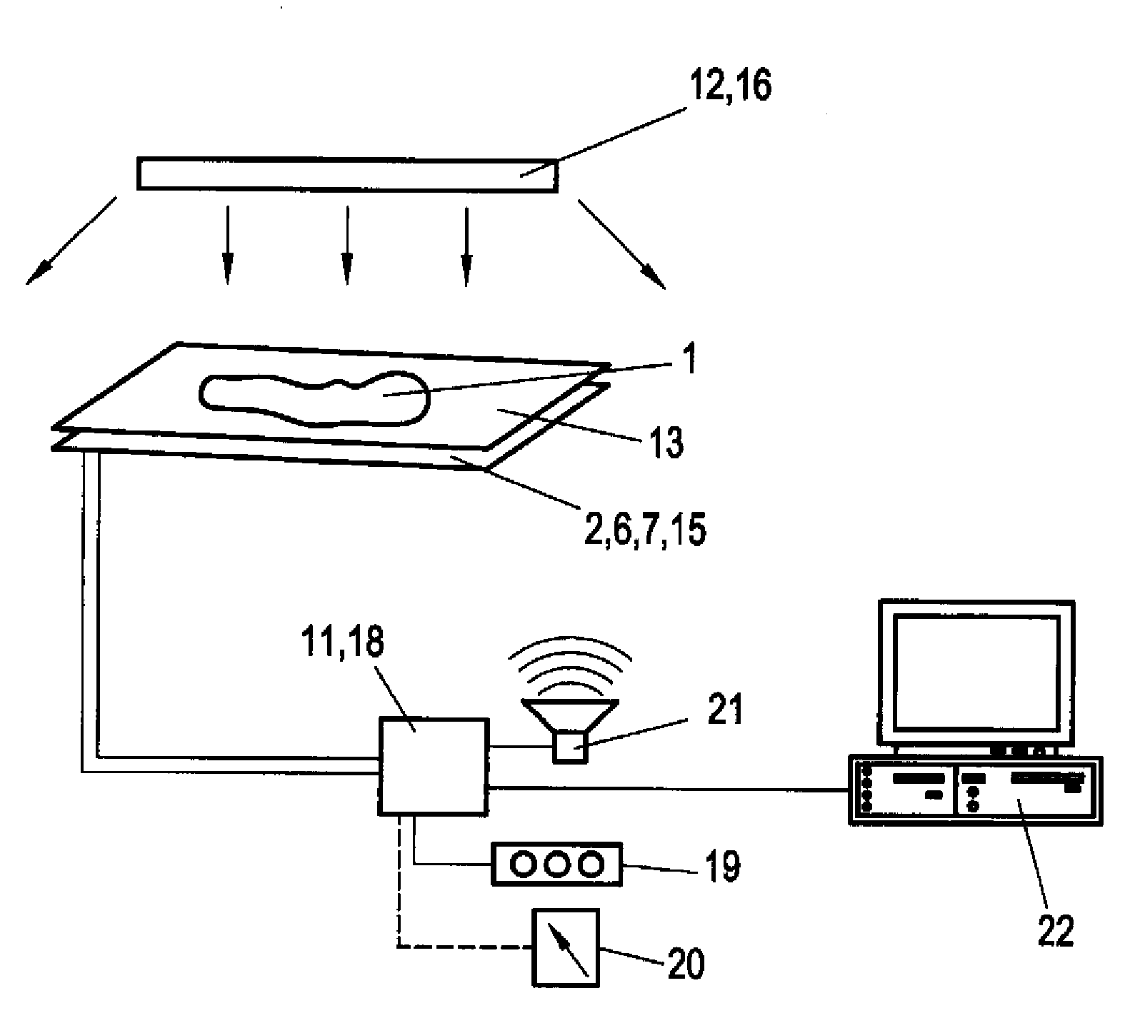
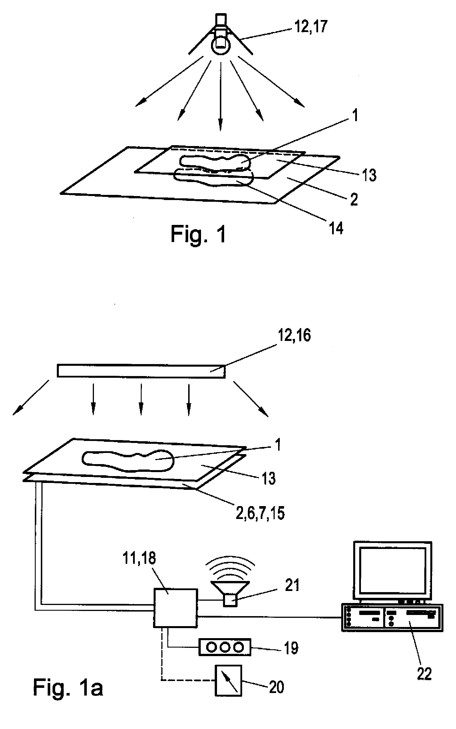
[0047]FIG. 1 shows the apparatus according to the invention, having a particularly simple design. The sample 1 is hereby arranged on a sample carrier and can be supplied either in solid form, for example as a thin layer, as a powder, a fluid or a gas. In operation, an optical measuring device 2, which has partially reflecting and partially transparent material, is arranged below the sample carrier 13. For example, this may be a uniform white thin foil made of paper, plastic or the like. In an embodiment according to FIG. 1, an illumination unit 12, for example a spot light 17, may be provided. The spot light 17 which may represent a substantially point-like light source, may cast a shadow 14 of the sample 1 and the sample holder 13 onto the optical measuring device 2 located below. Other illumination units 12, for example neon tubes, projection lamps or even ambient light can be used instead of the spot light. Preferably, the illumination unit 12 should cast a significant shadow 14 ...

third embodiment

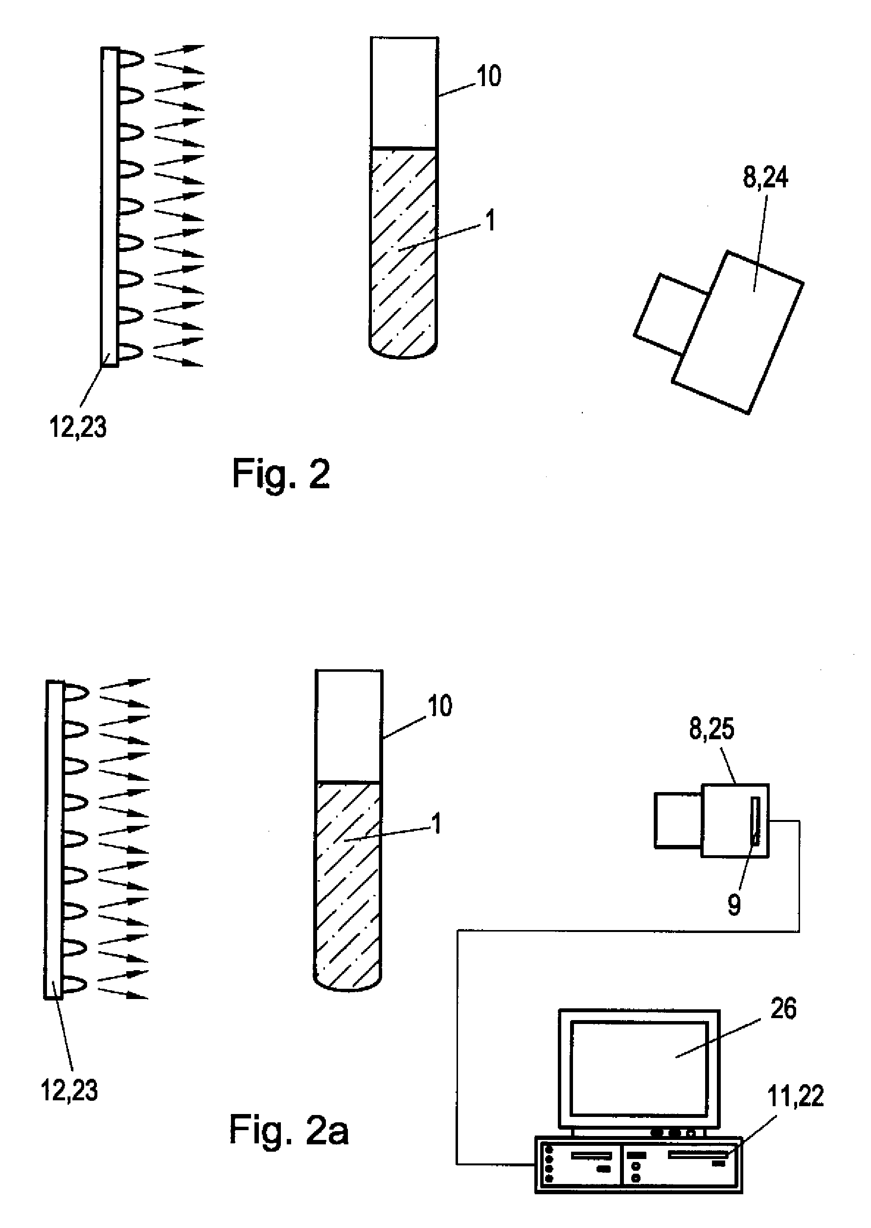
[0051]FIG. 2 shows an apparatus according to the invention, having a transparent test tube 10 and a powder or sample fluid 1 disposed in the test tube 10. the sample can be uniformly illuminated with an illumination unit 12, illustrated in FIG. 2 as an LED array 23, so that the sample 1 is always uniformly illuminated even when the ambient light level changes. A camera 8, for example an instant camera 24, is mounted so as to be in the visual contact with the sample 1, acquiring an image of the sample 1 before each measurement.

[0052]The instant camera 24 can be placed so that the sample is located between the illumination unit 12 and the camera 8 or in another position advantageous for acquiring an image of the sample 1. The acquired image shows within several minutes an accurate and detailed representation of the sample 1 and the test tube 10. Both the homogeneity in brightness and color of the sample, as well as any inhomogeneity 3, in particular caused by air inclusions 4 and / or c...


PUM


Abstract

A device for determining a physical quantity of a sample, in particular for determining the density of a fluid, is implemented as an optical measuring device which allows an evaluation the reliability of the measured value in the measurement of the physical quantity of the sample.

Description

CROSS-REFERENCES TO RELATED APPLICATIONS[0001]This application claims the priority of Austrian Patent Application, Serial No. A 1698 / 2006, filed Oct. 12, 2006, pursuant to 35 U.S.C. 119(a)-(d), the content of which is incorporated herein by reference in its entirety as if fully set forth herein.BACKGROUND OF THE INVENTION[0002]The present invention relates to an apparatus for determining a physical quantity of a sample.[0003]Nothing in the following discussion of the state of the art is to be construed as an admission of prior art.[0004]An apparatus for determining the density of fluids according to the oscillator principle in compliance with ISO 15212-1:1998 is known to include a density sensor which can be readily filled with the sample or which is immersed in the sample, a device for exciting and monitoring the oscillation of the density sensor, a device for determining and displaying the density, the oscillation frequency or period, a device for determining and displaying the sa...

Claims


Application Information

Patent Timeline
IPC IPC(8): G02B27/32
CPCG01N21/94G01F23/292
Inventor SENN, HELMUTHRITZMANN, KLAUSBELITSCH, WOLFGANG
Owner LABOR FUER MESSTECHN DR HANS STABINGER
Why Eureka
Try Eureka