Magnetic head for perpendicular magnetic recording

a magnetic recording and perpendicular magnetic technology, applied in the direction of magnetic recording heads, data recording, instruments, etc., can solve the problems of reducing the flux density of the middle magnetic layer, affecting the quality of the magnetic recording, so as to prevent the reduction of the flux density of the magnetic layer

Inactive Publication Date: 2008-04-17
HEADWAY TECH INC +1
View PDF9 Cites 5 Cited by
  • Summary
  • Abstract
  • Description
  • Claims
  • Application Information

AI Technical Summary

Benefits of technology

[0023]It is an object of the invention to provide a magnetic head for perpendicular magnetic recording comprising a magnetic layer generating a write magnetic field and two coils located to sandwich the magnetic layer, the head being capable of preventing a reduction in flux density of the magnetic layer.

Problems solved by technology

On the other hand, if the track width is reduced, the write characteristics, such as an overwrite property that is a parameter indicating an overwriting capability, suffers degradation.
In a magnetic disk drive of the perpendicular magnetic recording system that exhibits a better capability of writing on a recording medium than the longitudinal magnetic recording system, in particular, if the above-mentioned skew occurs, problems arise, such as an occurrence of a phenomenon in which data stored on an adjacent track is erased when data is written on a specific track (that is hereinafter called adjacent track erase), or unwanted writing between adjacent two tracks.
However, the magnetic heads disclosed in U.S. Pat. No. 4,672,493 and U.S. Pat. No. 6,954,340 B2 have problems as will now be described.
As a result, in the middle magnetic layer of this magnetic head, there occurs repulsion between the magnetic flux that has come into the middle magnetic layer from the magnetic layer located forward and the magnetic flux that has come into the middle magnetic layer from the magnetic layer located backward, and the flux density of the middle magnetic layer may be thereby reduced, which may result in degradation of overwrite property.
As a result, in the main pole of this magnetic head, there occurs repulsion between the magnetic flux that has come into the main pole from the return pole located forward via the first magnetic stud and the magnetic flux that has come into the main pole from the return pole located backward via the second magnetic stud, and the flux density of the main pole may be thereby reduced, which may result in degradation of overwrite property.

Method used


Image

  • Magnetic head for perpendicular magnetic recording
  • Magnetic head for perpendicular magnetic recording
  • Magnetic head for perpendicular magnetic recording

Examples


first embodiment

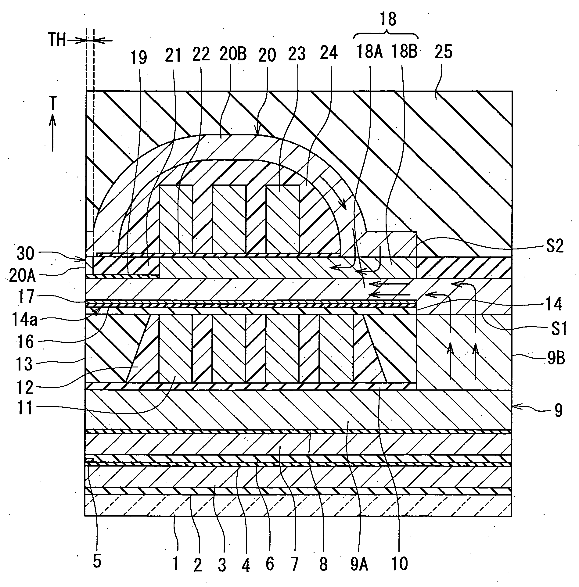
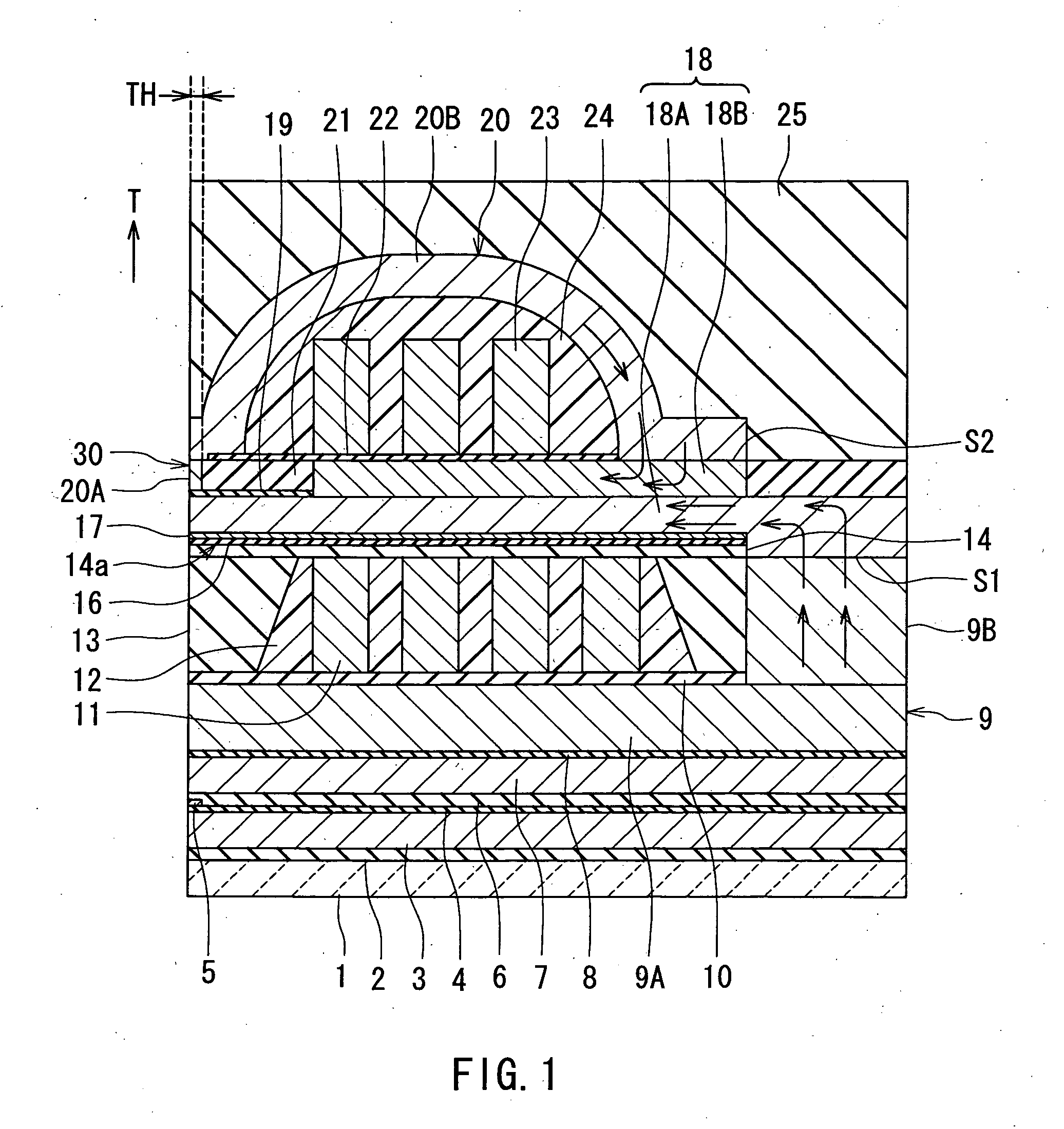
[0083]Preferred embodiments of the invention will now be described in detail with reference to the accompanying drawings. Reference is now made to FIG. 1 to FIG. 3 to describe the configuration of a magnetic head for perpendicular magnetic recording of a first embodiment of the invention. FIG. 1 is a cross-sectional view for illustrating the configuration of the magnetic head of the embodiment. FIG. 1 illustrates a cross section orthogonal to the medium facing surface and the plane of a substrate. The arrow indicated with T in FIG. 1 shows the direction of travel of a recording medium. The arrow with T denotes the same in the other drawings, too. FIG. 2 is a front view of the medium facing surface of the magnetic head of the embodiment. FIG. 3 is a top view of a pole layer of the magnetic head of the embodiment.

[0084]As shown in FIG. 1 and FIG. 2, the magnetic head for perpendicular magnetic recording (hereinafter simply called the magnetic head) of the embodiment comprises: a subst...

second embodiment

[0152]Reference is now made to FIG. 12 to describe a magnetic head of a second embodiment of the invention. FIG. 12 is a cross-sectional view for illustrating the configuration of the magnetic head of the second embodiment. FIG. 12 illustrates a cross section orthogonal to the medium facing surface and the plane of the substrate.

[0153]In the magnetic head of the second embodiment, the insulating layer 13 is provided to cover the first coil 11 and the insulating layer 12. The insulating layer 13 and the second layer 9B have flattened top surfaces.

[0154]In the second embodiment a lower yoke layer 18C is provided in place of the upper yoke layer 18B of the first embodiment. The magnetic layer 18 for writing of the second embodiment incorporates the pole layer 18A and the lower yoke layer 18C. The lower yoke layer 18C is connected to the pole layer 18A and disposed backward of the pole layer 18A along the direction T of travel of the recording medium at a location away from the medium f...

third embodiment

[0165]Reference is now made to FIG. 13 to FIG. 15 to describe a magnetic head of a third embodiment of the invention and a method of manufacturing the same. Each of FIG. 13 to FIG. 15 is a cross-sectional view for illustrating the configuration of the magnetic head of the third embodiment. Each of FIG. 13 to FIG. 15 illustrates a cross section orthogonal to the medium facing surface and the plane of the substrate.

[0166]The magnetic head of the third embodiment is similar to the magnetic head of the first embodiment but has differences as will now be described. In the magnetic head of the third embodiment, when seen in the direction orthogonal to the interface S2 between the second layer 20B and the upper yoke layer 18B, at least part of the interface S2 is disposed at a location that coincides with at least part of the interface S1 between the second layer 9B and the pole layer 18A. The magnetic head of the third embodiment has a nonmagnetic layer 28B made of a nonmagnetic material ...


PUM

PropertyMeasurementUnit
heightaaaaaaaaaa
thicknessaaaaaaaaaa
thicknessaaaaaaaaaa

Abstract

A magnetic layer for writing incorporates: a pole layer having an end face located in a medium facing surface; and an upper yoke layer. A first magnetic layer for flux concentration is connected to the pole layer at a location away from the medium facing surface, and allows a magnetic flux corresponding to a magnetic field generated by a first coil to pass. A second magnetic layer for flux concentration is connected to the upper yoke layer at a location away from the medium facing surface, and allows a magnetic flux corresponding to a magnetic field generated by a second coil to pass. When seen in the direction orthogonal to the interface between the second magnetic layer and the upper yoke layer, this interface is disposed at a location that does not coincide with the interface between the first magnetic layer and the pole layer.

Description

BACKGROUND OF THE INVENTION[0001]1. Field of the Invention[0002]The present invention relates to a magnetic head for perpendicular magnetic recording that is used for writing data on a recording medium by means of a perpendicular magnetic recording system.[0003]2. Description of the Related Art[0004]The recording systems of magnetic read / write devices include a longitudinal magnetic recording system wherein signals are magnetized in the direction along the surface of the recording medium (the longitudinal direction) and a perpendicular magnetic recording system wherein signals are magnetized in the direction orthogonal to the surface of the recording medium. It is known that the perpendicular magnetic recording system is harder to be affected by thermal fluctuation of the recording medium and capable of implementing higher linear recording density, compared with the longitudinal magnetic recording system.[0005]Like magnetic heads for longitudinal magnetic recording, magnetic heads f...

Claims


Application Information

Patent Timeline
Patent Type & Authority Applications(United States)
IPC IPC(8): G11B5/127
CPCG11B5/1278
Inventor SASAKI, YOSHITAKAITOH, HIROYUKITANEMURA, SHIGEKISHIMIZU, TATSUSHISHIMIZU, TATSUYA
Owner HEADWAY TECH INC
Why Eureka
Try Eureka