Image forming apparatus

Inactive Publication Date: 2008-04-17
CANON KK
View PDF5 Cites 16 Cited by
  • Summary
  • Abstract
  • Description
  • Claims
  • Application Information

AI Technical Summary

Benefits of technology

[0014] It is an object of the present invention to provide an image forming technique capable of stably detecting a registration correction pattern even if the toner density of the registration correction pattern or the reflectance of the belt surface changes.
[0015] It is another object of the present invention to provide an image forming technique capable of prolonging the service life of the light-emitting portion of a correction pattern detection sensor by setting a minimum light amount value to stably detect a registration correction pattern.
[0017] The present invention can stably detect a light amount adjustment pattern even if the toner density of the light amount adjustment pattern or the reflectance of the surface of the image carrier belt changes.
[0018] The present invention can prolong the service life of the light-emitting portion of a correction pattern detection sensor by setting a minimum light amount value to stably detect a light amount adjustment pattern.

Problems solved by technology

This method may suffer a registration correction pattern detection error if the difference in the amount of reflected light between the underlayer and the registration correction pattern becomes small as a result of, for example, contaminating the intermediate transfer belt or the light-receiving portion, or decreasing the amount of light of the light-emitting portion of the correction pattern detection sensor upon a change over time.
No sufficient difference in amount of reflected light can be ensured between the intermediate transfer belt and the registration correction pattern.
If, for example, the amount of reflected light from the intermediate transfer belt decreases under the influence of a scratch or the like on the intermediate transfer belt, the correction pattern may be erroneously detected.
However, an excessive amount of light is projected by adjustment to increase the amount of irradiating light of the light-emitting portion so as to raise the received amount of light from the surface of the intermediate transfer belt to a given value though the registration correction pattern can be accurately determined.
This shortens the service life of the light-emitting portion.
However, this reference does not disclose adjustment of the amount of irradiating light of the sensor.

Method used


Image

  • Image forming apparatus
  • Image forming apparatus
  • Image forming apparatus

Examples


first embodiment

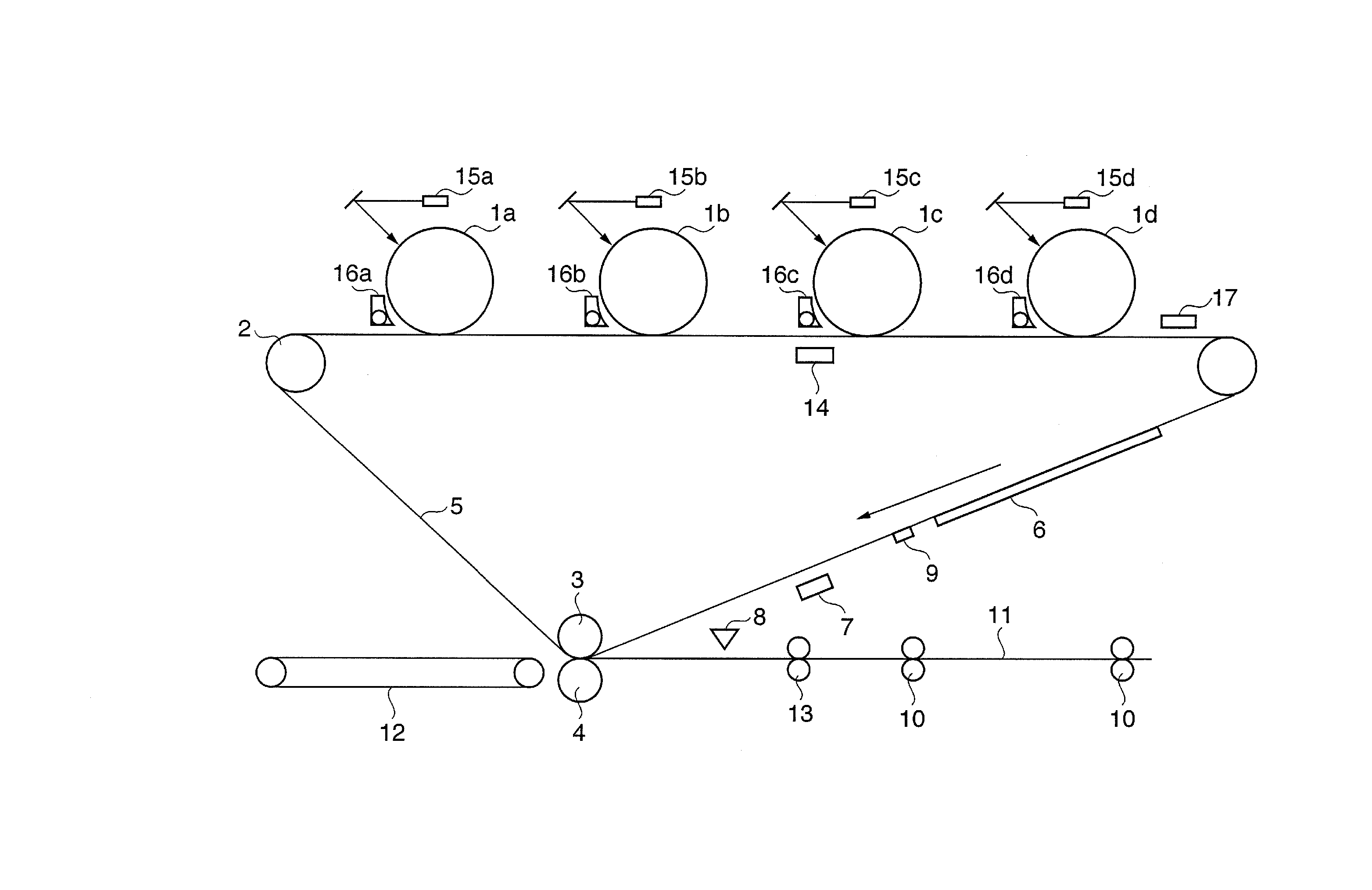
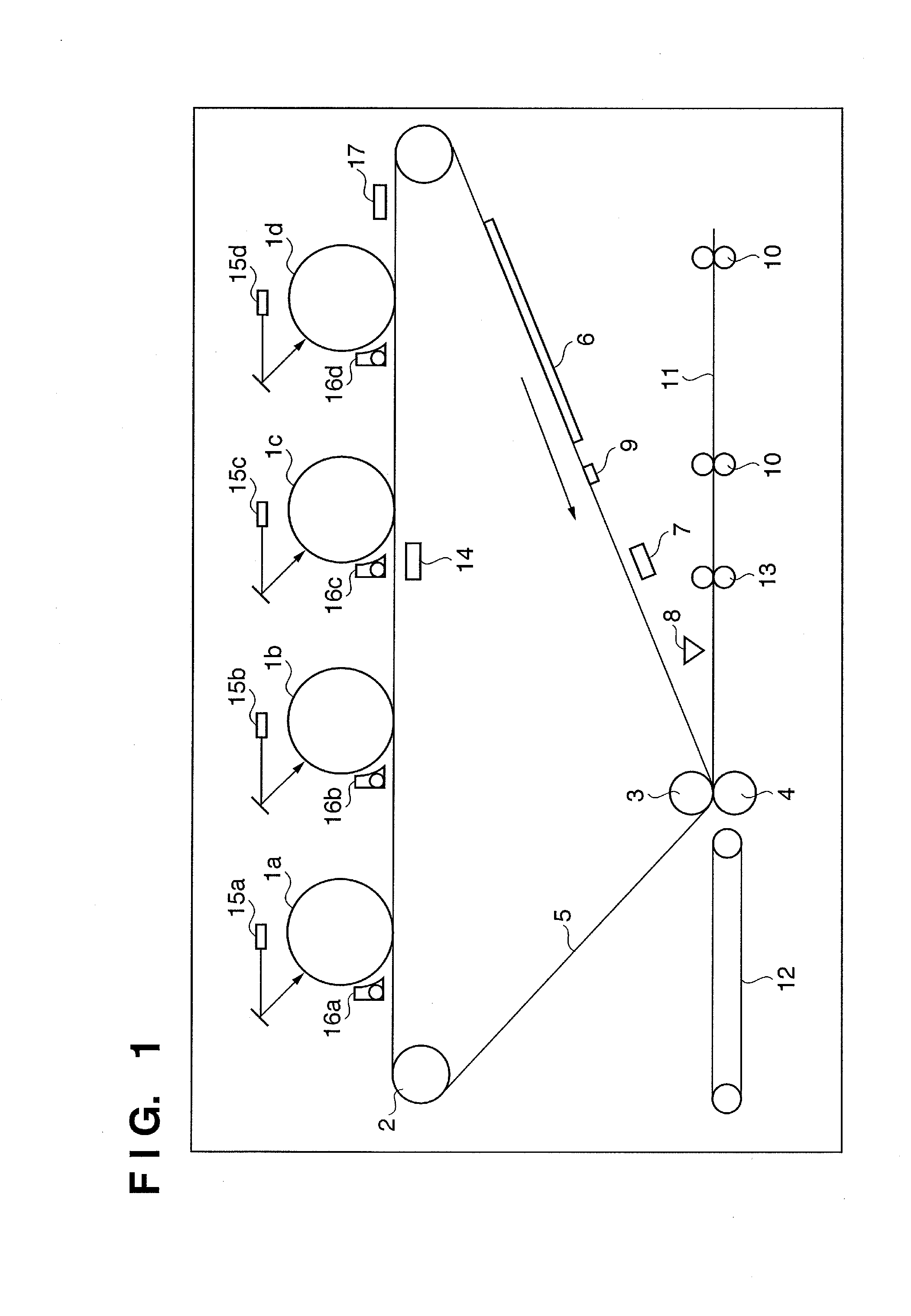
[0037]FIG. 1 is a sectional view for explaining the schematic arrangement of an image forming section in an image forming apparatus according to the embodiment.

[0038] (Arrangement of Image Forming Section)

[0039] In FIG. 1, laser writing units 15a, 15b, 15c, and 15d are arranged in order of yellow (Y), cyan (C), magenta (M), and black (B). Developing units 16a, 16b, 16c, and 16d develop latent images formed on photosensitive drums 1a, 1b, 1c, and 1d serving as image carriers by the laser writing units 15a, 15b, 15c, and 15d. The toner images formed on the photosensitive drums 1a, 1b, 1c, and 1d are sequentially transferred over each other on an image carrier belt (to be referred to as an “intermediate transfer belt” hereinafter) 5, forming a color toner image 6.

[0040] Color registration, and registration between a sheet and each color toner image are done based on the detection result of a color position adjustment sensor 17.

[0041] The color toner image 6 is transferred onto a sh...

second embodiment

[0083] Adjustment of amount of light by an image forming apparatus according to the second embodiment will be explained. FIG. 4 is a flowchart for explaining the sequence of adjustment of amount of light in the image forming apparatus according to the second embodiment. The adjustment of amount of light is executed under the control of a CPU 108. The same step numbers as those in the adjustment of amount of light (FIG. 3) according to the first embodiment denote the same processes, and a description thereof will not be repeated. Steps S301 to S304 and S306 to S310 are the same processes as those in the adjustment of amount of light according to the first embodiment.

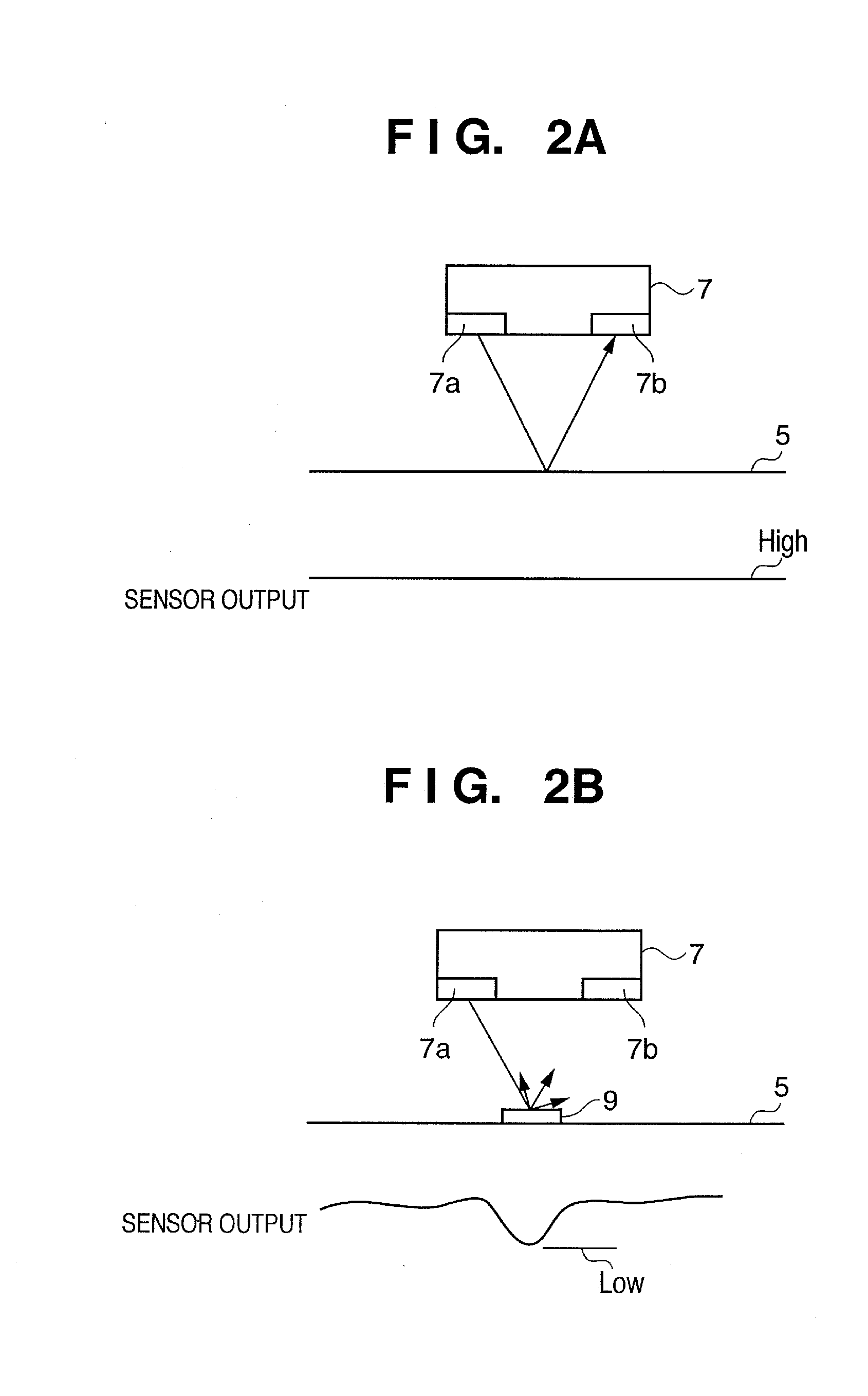
[0084] In step S401, the CPU 108 measures the dark voltage of a light-receiving portion 7b of a correction pattern detection sensor 7, and outputs the measurement result as an amount of reflected light from the surface of an intermediate transfer belt 5 with respect to the minimum amount of irradiating light.

[0085] The ...

third embodiment

[0092] Adjustment of amount of light by an image forming apparatus according to the third embodiment will be explained. FIG. 5 is a flowchart for explaining the sequence of adjustment of amount of light in the image forming apparatus according to the third embodiment. The adjustment of amount of light is executed under the control of a CPU 108. The same step numbers as those in the adjustments of amount of light (FIGS. 3 and 4) according to the first and second embodiments denote the same processes, and a description thereof will not be repeated.

[0093] Steps S301 to S304, S306, and S307 are the same processes as those in the adjustment of amount of light according to the first embodiment. S401 is the same process as that in the adjustment of amount of light according to the second embodiment.

[0094] In step S501, the CPU 108 controls a correction pattern detection sensor 7, and a light-emitting portion 7a changes the amount of irradiating light.

[0095] In step S309, a correction pa...


PUM


Abstract

An image forming apparatus includes a pattern forming unit which forms a light amount adjustment pattern on an image carrier belt, a light amount control unit which controls the amount of light irradiating the image carrier belt and pattern, a detection sensor which detects reflected light amounts from the image carrier belt and pattern with respect to the irradiating light amount and stores the detection results in a storage unit, a calculation unit which calculates the correspondence between the irradiating light amount and the reflected light amounts from the image carrier belt and pattern on the basis of the detection results and stores the calculation results in the storage unit, and a light amount decision unit which decides, on the basis of the calculation results, a light amount at which the difference between the reflected light amounts from the image carrier belt and pattern exhibits a value set in advance.

Description

BACKGROUND OF THE INVENTION [0001] 1. Field of the Invention [0002] The present invention relates to an electrophotographic image forming technique. [0003] 2. Description of the Related Art [0004] Some conventional image forming apparatuses such as a printer, copying machine, and facsimile apparatus transfer, onto conveyed paper, a toner image formed on an image carrier (intermediate transfer belt). To correct the position and color misregistration of an image formed on paper, an image forming apparatus of this type forms a reference image (registration correction pattern) on an intermediate transfer belt, detects it, and calculates the positional error amount (registration error amount). The image forming apparatus corrects color misregistration and the position of an image formed on paper based on the calculation result (image position correction). [0005] To detect the registration correction pattern, a predetermined current is supplied to the light-emitting portion of a correctio...

Claims


Application Information

Patent Timeline
IPC IPC(8): G03G15/04
CPCG03G15/0194G03G2215/0161
Inventor TAKEZAWA, SATORUNAKAZATO, JUNKODAMA, HIROKAZU
Owner CANON KK
Why Eureka
Try Eureka