Vacuum adsorbing apparatus for fan positioning

a technology of vacuum adsorption and fan positioning, which is applied in the direction of non-positive displacement fluid engines, pump components, reaction engines, etc., can solve the problems of reducing the pre-operation time of fan molding, reducing the effectiveness of fixing, and wasting all previous efforts.

Inactive Publication Date: 2008-04-17
INVENTEC CORP
View PDF2 Cites 1 Cited by
  • Summary
  • Abstract
  • Description
  • Claims
  • Application Information

AI Technical Summary

Benefits of technology

[0007]In view of the above, the problem that the present invention intends to solve is to provide a fan positioning apparatus which can rapidly fix the fan to a given position without using ribs or filling wax or lime, thereby decreasing the pre-operation time of fan molding and effectively reducing the positioning costs spent during fan positioning.
[0008]In order to solve the problems of the above-mentioned techniques, the present invention provides a vacuum adsorbing apparatus for fan positioning, which comprises a fan, a fixing frame, and a vacuum aspirator. The fixing frame has a plurality of workpiece holders each having a through-hole in its center, the through-holes are in communication with a plurality of air flues provided in the workpiece holders, and the vacuum aspirator is connected with the through-holes via the air flues by utilizing a plurality of air pipes. When performing the molding operation of the fan, the fan is first placed onto the workpiece holder, and the vacuum aspirator is then actuated. The vacuum aspirator generates a powerful suction force, such that the fan may be fixed to the workpiece holder due to the suction force, thus facilitating the operation of molding the fan and finely tuning the fan blades. After finishing the molding or the fine tune of the blades, the finished product of the fan can be taken off as long as the vacuum aspirator is switched-off. Meanwhile, the through-holes further comprise a thread so that the workpiece holders can be connected with the air flues through screwing.
[0009]A vacuum adsorbing apparatus for fan positioning provided by the present invention has the following structure which is better than that of the prior art in several ways, and gains significant improvements in its performance as set forth below.
[0010]1. Low cost. It is possible to make the standard molds based on the desired shape of the fan, thus the time and costs taken for pre-operation may be reduced.

Problems solved by technology

Conventionally, the most important moment during CNC's manufacturing of fan lies in the molding and cutting of the fan, since it is the last stage before having the product finished, and all previous efforts will go wasted if we fail to handle it well.
(1) The disadvantage of fixing the fan by ribs is the need to trim the fan blade after its molding, however, since the trimming has to be done manually, the damage of fan blade due to overexerting occurs frequently.
Still, the fan cannot be effectively fixed by filling wax or utilizing lime during its molding operation, so the swaying or shifting of fan occurs frequently, which therefore leads to the failure of the molding operation of the fan.

Method used


Image

  • Vacuum adsorbing apparatus for fan positioning
  • Vacuum adsorbing apparatus for fan positioning
  • Vacuum adsorbing apparatus for fan positioning

Examples


Embodiment Construction

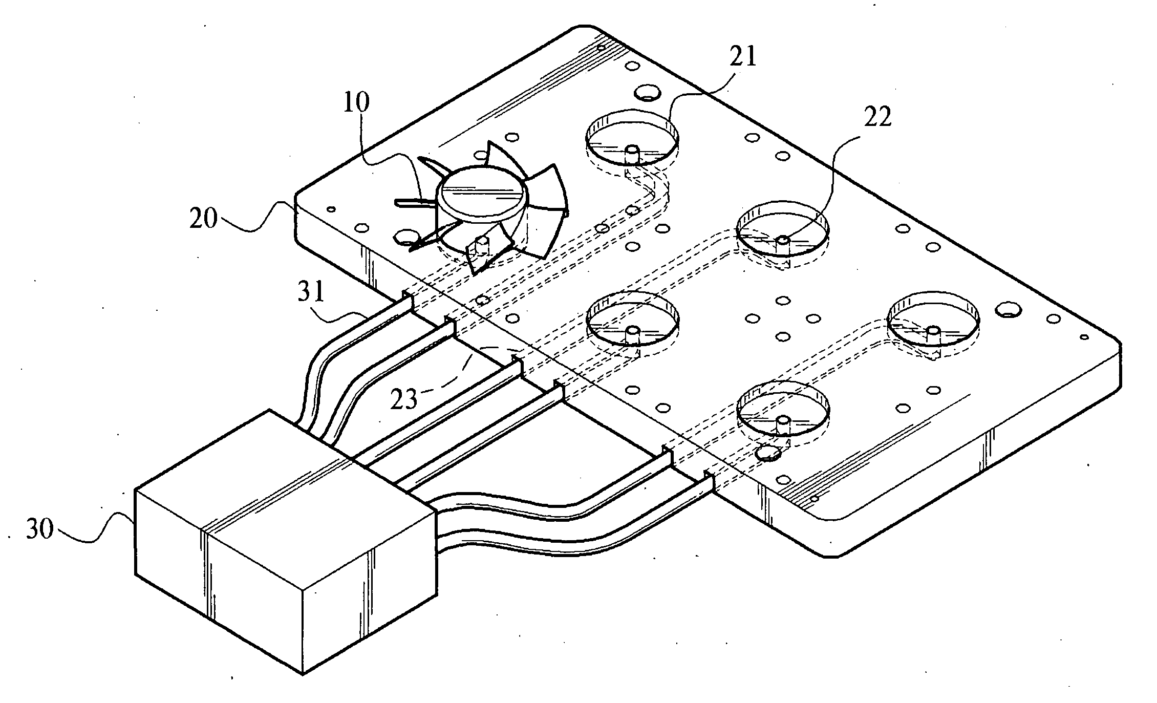
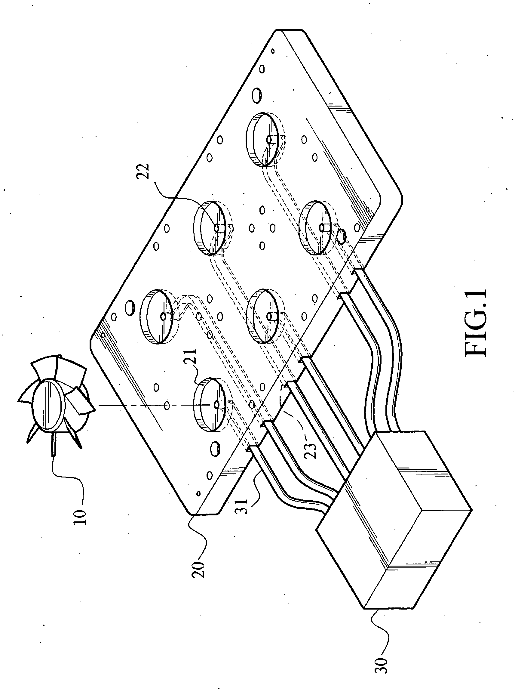
[0018]As shown in FIG. 1, it is a basic architectural schematic view of the present invention, which includes at least one fan 10, a fixing frame 20, and a vacuum aspirator 30. The fixing frame 20 has a plurality of workpiece holders 21 thereon, and the fan 10 may be arranged in any one of the workpiece holders 21. The workpiece holders 21 are each provided with a through-hole 22 in its center, and the fan 10 may form a closed space with the through-hole 22 when placed onto the workpiece holder 21. The fixing frame 20 is provided with a plurality of air flues 23 in communication with corresponding through-holes 22. The vacuum aspirator 30 has a plurality of air pipes 31 connected to the through-holes 22 via the air flues 23. And the through-hole 22 is further provided with a thread (not shown) for the air pipe 31 to be screwed thus forming a state of being closely connected.

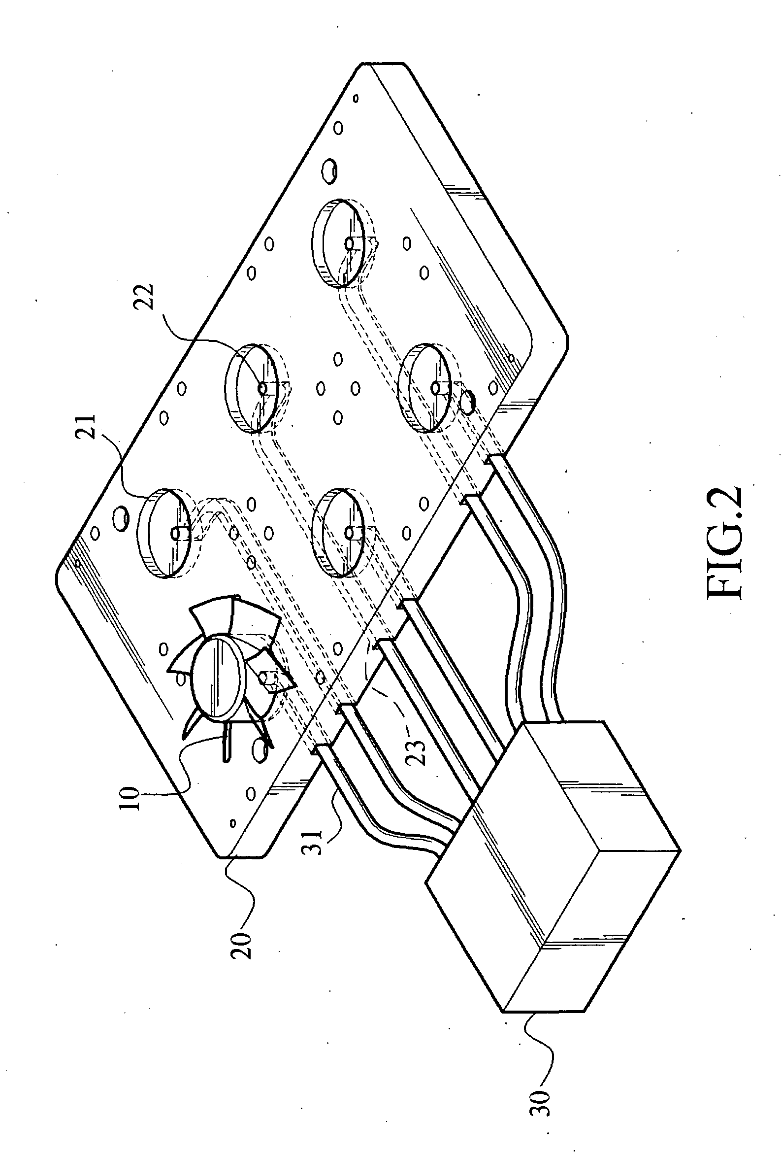
[0019]As shown in FIG. 2, it is a schematic view showing that the fan 10 is fixed to the fixing frame 20. The ...


PUM


Abstract

A vacuum adsorbing apparatus for fan positioning is provided, which includes a fixing frame and a vacuum aspirator. The fixing frame has a workpiece holder to provide close arrangement for the fan, and a through-hole connected with the vacuum aspirator is disposed in the workpiece holder corresponding to the arranged position of the fan, so as to pump out the air in the closed space between the through-hole and the fan when the vacuum aspirator actuates, thus positioning the fan on the fixing frame due to the suction force.

Description

BACKGROUND OF THE INVENTION[0001]1. Field of Invention[0002]The present invention relates to a vacuum adsorbing apparatus for fan positioning, and more particularly to a fixing apparatus for fixing an unmolded fan to a fixing frame with vacuum adsorbing when performing the molding operation of the fan.[0003]2. Related Art[0004]Conventionally, the most important moment during CNC's manufacturing of fan lies in the molding and cutting of the fan, since it is the last stage before having the product finished, and all previous efforts will go wasted if we fail to handle it well. Therefore, some CNC processing plants may utilize ribs to fix the fan during the molding, or may fix the fan to the fixing frame by filling wax or lime and then perform the molding operation of the fan. But the following unavoidable disadvantages will be incurred.[0005](1) The disadvantage of fixing the fan by ribs is the need to trim the fan blade after its molding, however, since the trimming has to be done ma...

Claims


Application Information

Patent Timeline
Patent Type & Authority Applications(United States)
IPC IPC(8): F04D29/00
CPCF04D29/388
Inventor CHEN, WIN-HAW
Owner INVENTEC CORP
Why Eureka
Try Eureka