Positioning method, positioning device and terminal equipment
A positioning device and positioning method technology, applied in the field of data processing, can solve the problems of high cost, poor accuracy, and susceptibility to interference, and achieve the effect of reducing positioning costs
- Summary
- Abstract
- Description
- Claims
- Application Information
AI Technical Summary
Problems solved by technology
Method used
Image
Examples
Embodiment 1
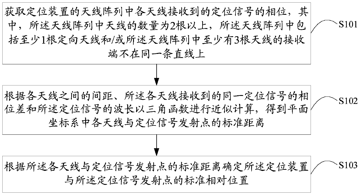
[0038] A positioning method provided by Embodiment 1 of the present application is described below, please refer to the attached figure 1 , the positioning method in Embodiment 1 of the present application includes:
[0039] Step S101. Obtain the phase of the positioning signal received by each antenna in the antenna array of the positioning device, wherein the number of antennas in the antenna array is more than two, and the antenna array includes at least one directional antenna and / or all The receiving ends of at least 3 antennas in the antenna array are not on the same straight line;
[0040] Directional antenna (Directional antenna) refers to an antenna that transmits and receives electromagnetic waves in one or several specific directions that are particularly strong, while transmitting and receiving electromagnetic waves in other directions is zero or extremely small. Directional antennas can be The booster antenna can also be an ordinary antenna modified by the extern...
Embodiment 2
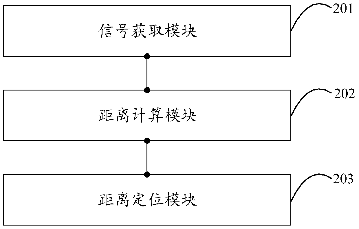
[0090] Embodiment 2 of the present application provides a positioning device. For the convenience of description, only the parts related to the present application are shown, such as figure 2 As shown, the positioning device includes,
[0091] The signal acquisition module 201 is configured to acquire the phase of the positioning signal received by each antenna in the antenna array of the positioning device, wherein the number of antennas in the antenna array is more than two, and the antenna array includes at least one directional antenna And / or the receiving ends of at least 3 antennas in the antenna array are not on the same straight line;
[0092] The distance calculation module 202 is used to perform approximate calculation with a trigonometric function according to the distance between the antennas, the phase difference of the same positioning signal received by the antennas, and the wavelength of the positioning signal, to obtain the distance between the antennas and t...
Embodiment 3
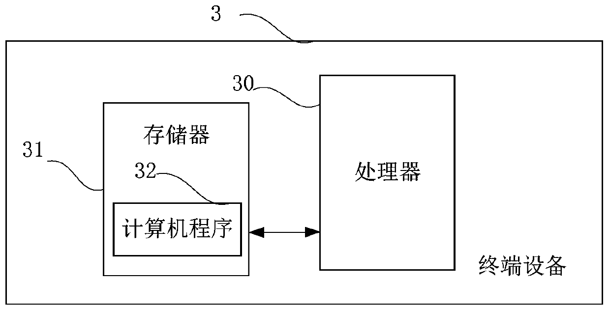
[0105] image 3 It is a schematic diagram of a terminal device provided in Embodiment 3 of the present application. Such as image 3 As shown, the terminal device 3 in this embodiment includes: a processor 30 , a memory 31 , and a computer program 32 stored in the memory 31 and operable on the processor 30 . When the processor 30 executes the computer program 32, the steps in the above embodiment of the positioning method are implemented, for example figure 1 Steps S101 to S103 are shown. Alternatively, when the processor 30 executes the computer program 32, it realizes the functions of the modules / units in the above-mentioned device embodiments, for example figure 2 The functions of modules 201 to 203 are shown.
[0106] Exemplarily, the computer program 32 can be divided into one or more modules / units, and the one or more modules / units are stored in the memory 31 and executed by the processor 30 to complete this application. The one or more modules / units may be a seri...
PUM
 Abstract
Description
Claims
Application Information
 - R&D
- Intellectual Property
- Life Sciences
- Materials
- Tech Scout
- Unparalleled Data Quality
- Higher Quality Content
- 60% Fewer Hallucinations
Browse by: Latest US Patents, China's latest patents, Technical Efficacy Thesaurus, Application Domain, Technology Topic, Popular Technical Reports.
© 2025 PatSnap. All rights reserved.Legal|Privacy policy|Modern Slavery Act Transparency Statement|Sitemap|About US| Contact US: help@patsnap.com


