

Manifold for Fuel Cell Stack
a fuel cell and stack technology, applied in the field of manifolds, can solve the problems of increasing energy loss, problematic dimensional restrictions in the tier direction of the manifold, etc., and achieve the effect of increasing energy loss
- Summary
- Abstract
- Description
- Claims
- Application Information
AI Technical Summary
Benefits of technology
Problems solved by technology
Method used
Image

Examples
first embodiment
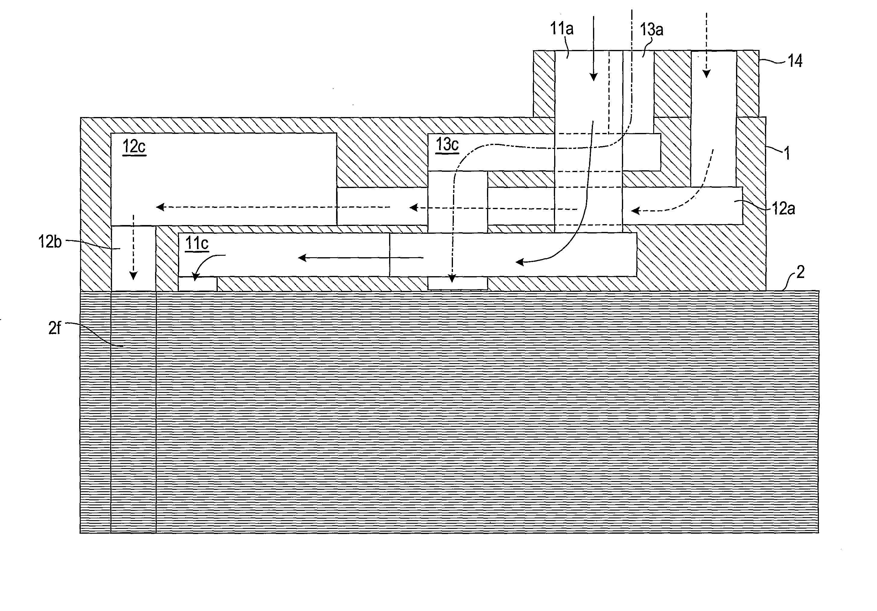
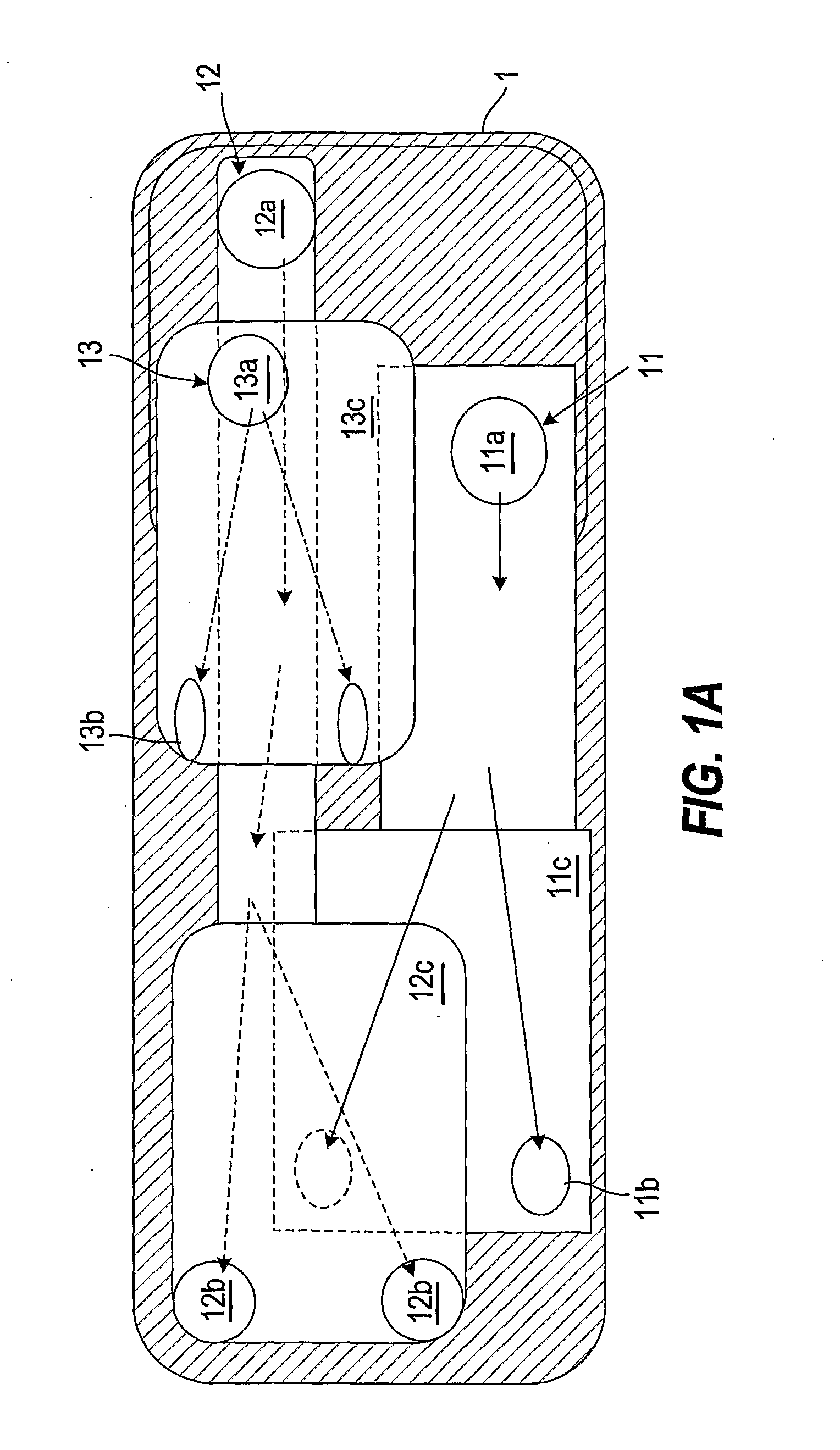
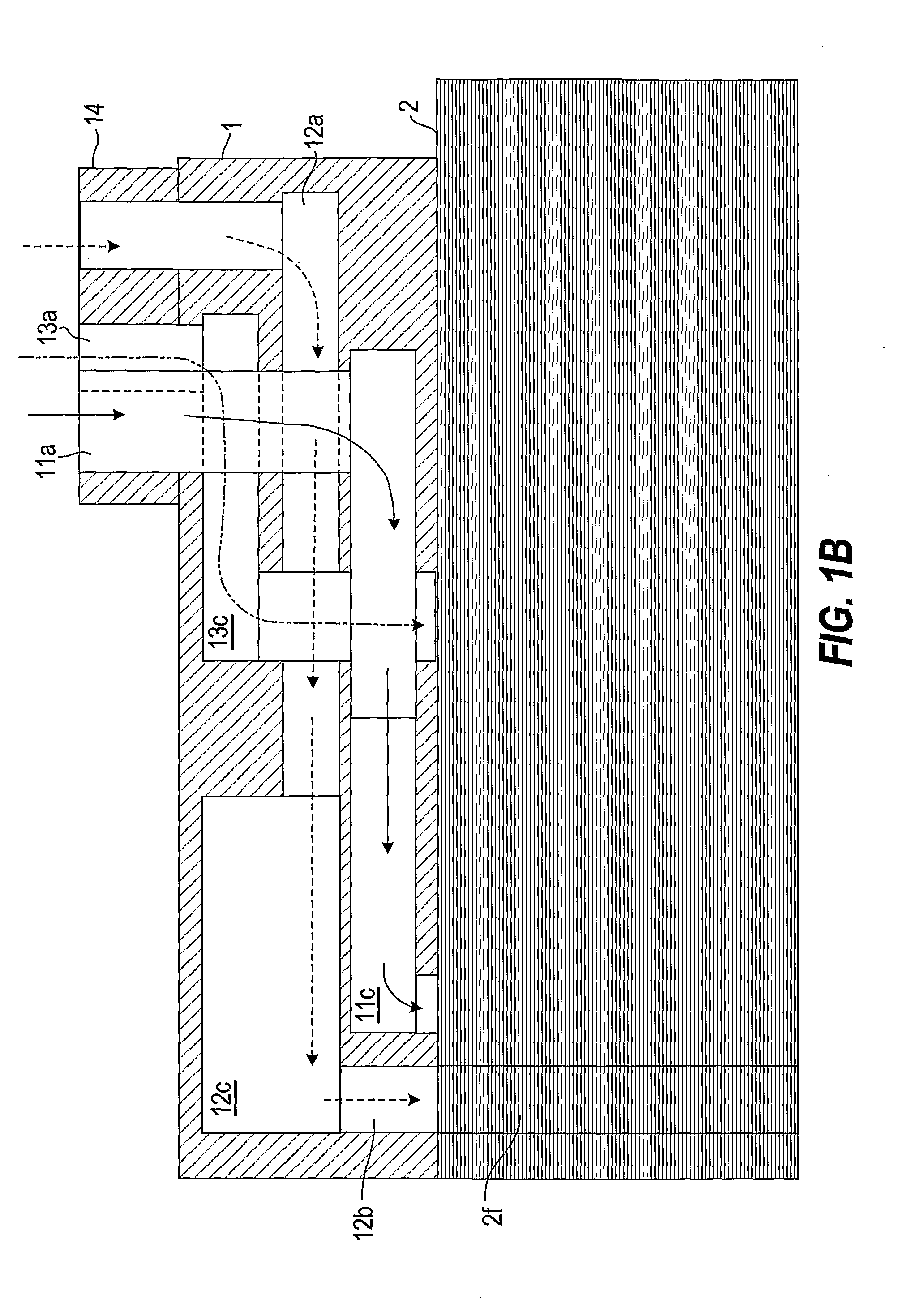
[0019]FIGS. 1A and 1B show a manifold 1 of a fuel cell stack 2 according to this invention. FIG. 1A illustrates a passage arrangement of the manifold 1 as a plan view, and FIG. 1B illustrates the passage arrangement of the same manifold 1 as a side view. The diagonally shaded parts of the drawings denote the material parts of the manifold 1, and the blank parts on the inside denote the passage parts. It should be noted that these drawings are illustrative views showing a passage arrangement, and therefore differ from a sectional view produced by a mechanical drawing method (this also applies to the drawings described below).
[0020] The manifold 1 is die-formed into an integral structure by subjecting resin to injection molding, casting, or a similar process. Three systems of passages 11-13 are formed to transport three types of fluid, constituted by a first fluid through a third fluid, to the fuel cell stack 2. For example, the first fluid is a cooling liquid, the second fluid is a f...
fifth embodiment
[0032]FIGS. 5A and 5B illustrate this invention. In this embodiment, the exterior side passages 11a-13a and interior side passages 11b-13b of the three passage systems 11-13 are assigned respectively to the three tiers, and the volume portions 11c-13c positioned in the respective intermediate parts are formed to penetrate the three tiers vertically. Further, as shown in FIG. 5A, the interior side passages 11b-13b of each system each bifurcate from the corresponding volume portion 11c-13c in three directions, and the interior side passages of the same system are all positioned in the same tier. More specifically, the three first interior side passages 11b are formed in the uppermost tier, the three second interior side passages 12b are formed in the middle tier, and the three third interior side passages 13b are formed in the lowest tier. By aligning the plurality of interior side passages on the same tier in this manner, it is possible to align the timing at which the fluid flows in...
sixth embodiment
[0034]FIGS. 6A and 6B illustrate this invention. In this embodiment, the manifold 1 is divided into a first manifold 1a and a second manifold 1b for supplying and discharging fluid through the respective three passage systems 11-13 thereof. The manifold 1 has an integral structure with the first manifold 1a and second manifold 1b separated from each other in the interior thereof. However, the first and second manifolds 1a, 1b may be formed as individual structures, as shown in FIG. 6C. One of the two manifolds 1a, 1b in this constitution is used to introduce fluid to the stack, and the other is used to discharge fluid from the stack. By dividing the manifold into a fluid supply manifold and a fluid discharge manifold in this manner, the freedom of the manifold arrangement in relation to the stack and the freedom of the pipe constitution in relation to the manifold can be increased.
[0035] In the constitution described above, by providing each of the first manifold 1a and second manif...
PUM
| Property | Measurement | Unit |
|---|---|---|
| volume | aaaaa | aaaaa |
| length | aaaaa | aaaaa |
| voltage | aaaaa | aaaaa |
Abstract
Description
Claims
Application Information