
Method And System For Identifying Radio Frequency Identification (RFID) Tag Location Using A Switchable Coil

a radio frequency identification and switchable coil technology, applied in the field of wireless communication, can solve the problems of limiting the ability to reduce the cost and size of rfid transponder circuits in rfid systems, antennas and/or coupling coils, and may be too large and bulky to integrate on the same integrated circuit chip with the rfid transponder circuit,

Active Publication Date: 2008-04-17
NXP USA INC
View PDF4 Cites 34 Cited by
  • Summary
  • Abstract
  • Description
  • Claims
  • Application Information

AI Technical Summary

Benefits of technology

[0034]A method and system for identifying a radio frequency identification (RFID) tag location using a switchable coil, substantially as shown in and / or described in connection with at least one of the figures, as set forth more completely in the claims.

Problems solved by technology

Two of the challenges in the development of radio frequency identification (RFID) systems are the inexorable quest to reduce the cost and size of RFID transponder circuits, and the need to provide secure communications environment between communicating RFID systems.
However, requirements associated with the design and implementation of passive components may limit the ability to reduce the cost and size of RFID transponder circuits in RFID systems.
For example, antennas and / or coupling coils, utilized to enable reception of signals at the RFID transponder circuit, may be too large and bulky to integrate on the same integrated circuit chip with the RFID transponder circuit.
Furthermore, circuitry that may enable secure communications based on the use of various data encryption algorithms may require levels of operating power consumption that are not practical for implementation in RFID systems.

Method used


Image

  • Method And System For Identifying Radio Frequency Identification (RFID) Tag Location Using A Switchable Coil
  • Method And System For Identifying Radio Frequency Identification (RFID) Tag Location Using A Switchable Coil
  • Method And System For Identifying Radio Frequency Identification (RFID) Tag Location Using A Switchable Coil

Examples


Embodiment Construction

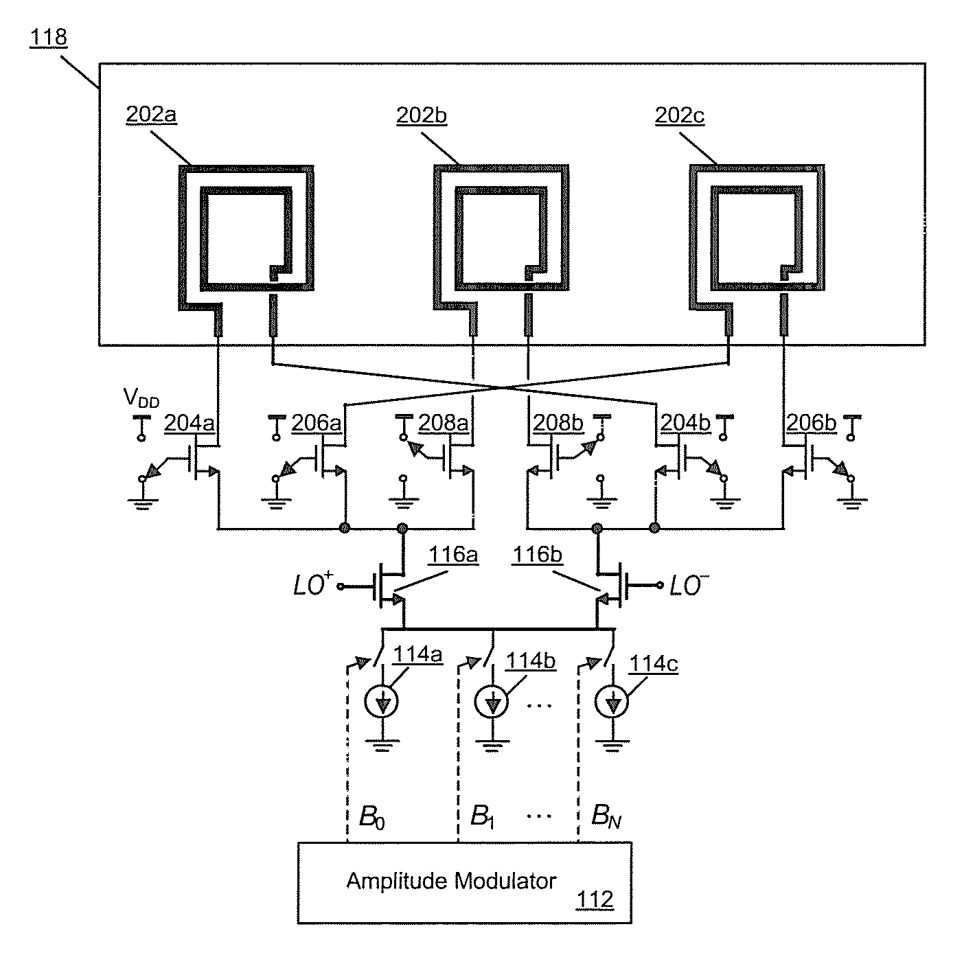
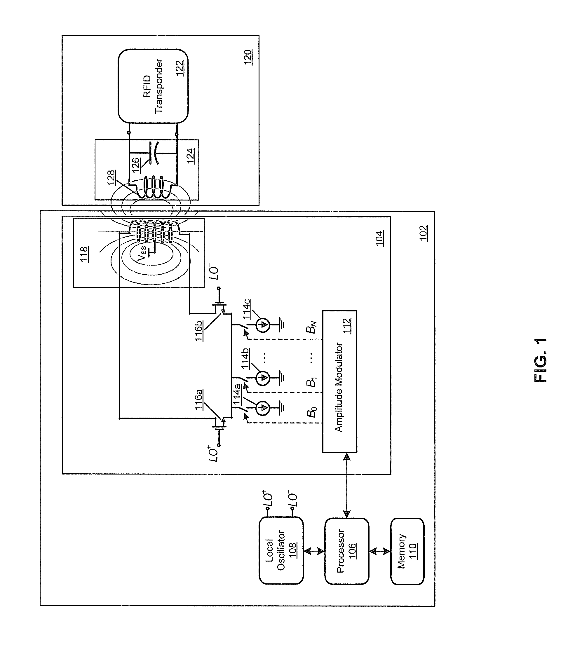
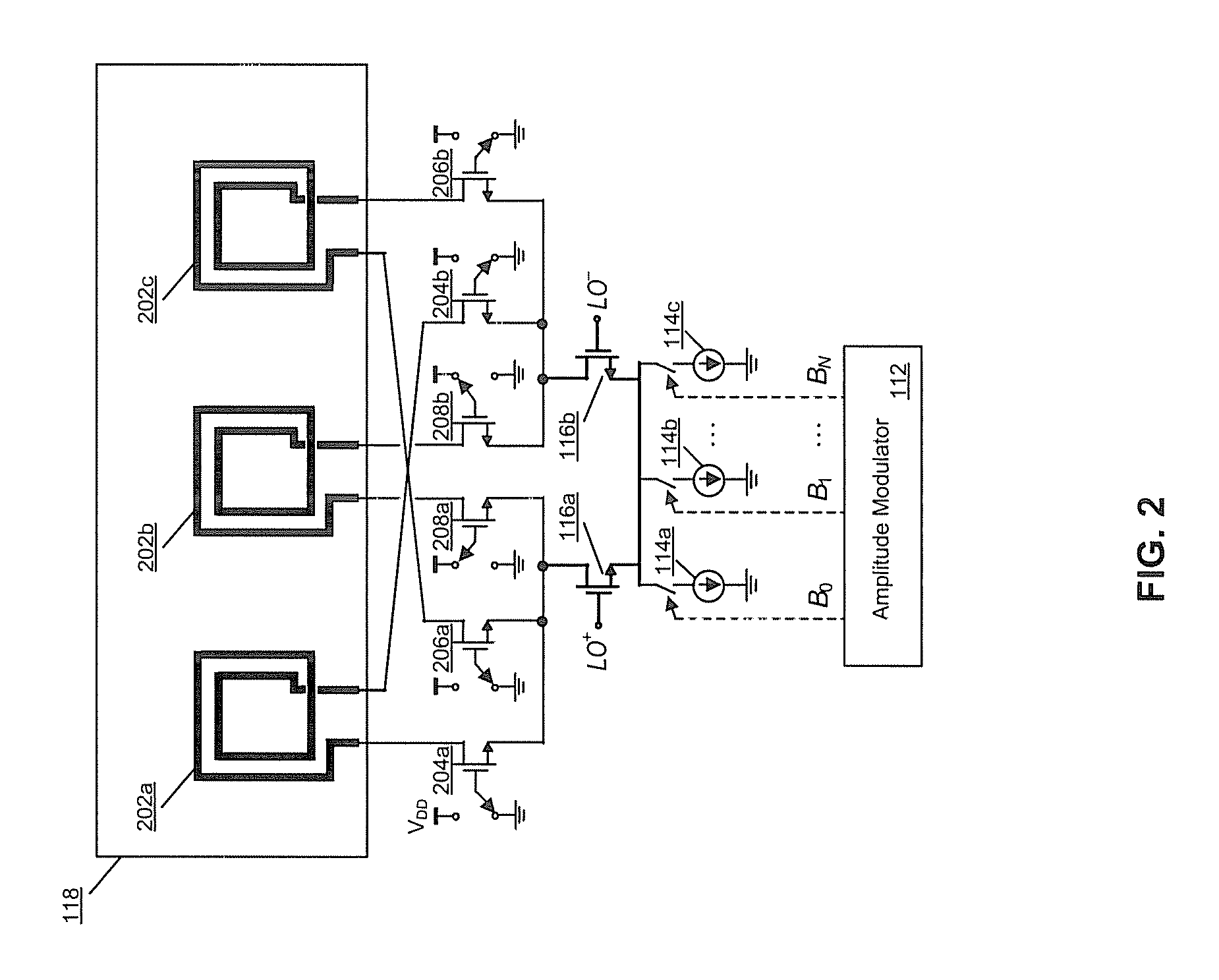
[0040]Certain embodiments of the invention may be found in a method and system for identifying a radio frequency identification (RFID) tag location using a switchable coil. In various embodiments of the invention, an RFID reader may select a current inductor coil from a plurality of inductor coils, which may be utilized for transmitting and / or receiving near field RFID signals having a frequency in the ultra high frequency (UHF) band. An exemplary UHF frequency band may comprise a range of frequencies from about 300 MHz to about 3 GHz. In an exemplary embodiment of the invention, the RFID signals may have a frequency of about 900 MHz. In various embodiments of the invention, RFID systems may communicate based on near field communications (NFC).

[0041]The RFID reader may utilize the selected inductor coil to detect the magnitude and / or direction of an electromagnetic field in the immediate vicinity of the RFID reader to determine whether an RFID transponder is located within the immed...


PUM


Abstract

Aspects of a method and system for identifying a radio frequency identification (RFID) tag location using a switchable coil are presented. Aspects of the systems may include one or more processors that enable selection of an inductor coil from a plurality of inductor coils. The selection of the inductor coil may be based on a change in an electromagnetic field, with respect to an initial electromagnetic field, as detected by the selected inductor coil. The processors may enable transmission of a signal, having a transmitter frequency in the UHF frequency band, via the selected inductor coil.

Description

CROSS-REFERENCE TO RELATED APPLICATIONS / INCORPORATION BY REFERENCE[0001]This application makes reference to:[0002]U.S. application Ser. No. ______ (Attorney Docket No. 17783US01), filed on even date herewith;[0003]U.S. application Ser. No. ______ (Attorney Docket No. 17784US01), filed on even date herewith;[0004]U.S. application Ser. No. ______ (Attorney Docket No. 17785US01), filed on even date herewith;[0005]U.S. application Ser. No. ______ (Attorney Docket No. 17786US01), filed on even date herewith;[0006]U.S. application Ser. No. ______ (Attorney Docket No. 17787US01), filed on even date herewith;[0007]U.S. application Ser. No. ______ (Attorney Docket No. 17788US01), filed on even date herewith;[0008]U.S. application Ser. No. ______ (Attorney Docket No. 17789US01), filed on even date herewith;[0009]U.S. application Ser. No. ______ (Attorney Docket No. 17790US01), filed on even date herewith;[0010]U.S. application Ser. No. ______ (Attorney Docket No. 17791US01), filed on even dat...

Claims


Application Information

Patent Timeline
Patent Type & Authority Applications(United States)
IPC IPC(8): H04B5/00
CPCH04B5/0075H04B5/0062H04B5/77H04B5/24
Inventor ROFOUGARAN, AHMADREZASHAMELI, AMIN
Owner NXP USA INC
Learn More