Bone Fusion Plate

a bone fusion and plate technology, applied in the field of bone fusion plates, can solve the problems of excess bone removal, limited wrist fusion, immobilization of virtually the entire wrist joint, etc., and achieve the effect of improving the retention of bone screws, facilitating the effective compression of bones together, and aggressive thread profil

a bone fusion and plate technology, applied in the field of bone fusion plates, can solve the problems of excess bone removal, limited wrist fusion, immobilization of virtually the entire wrist joint, etc., and achieve the effect of improving the retention of bone screws, facilitating the effective compression of bones together, and aggressive thread profil

US20080091198A1Inactive Publication Date: 2008-04-17MAYO FOUND FOR MEDICAL EDUCATION & RES

Image

  • Bone Fusion Plate
  • Bone Fusion Plate
  • Bone Fusion Plate

Examples


Embodiment Construction

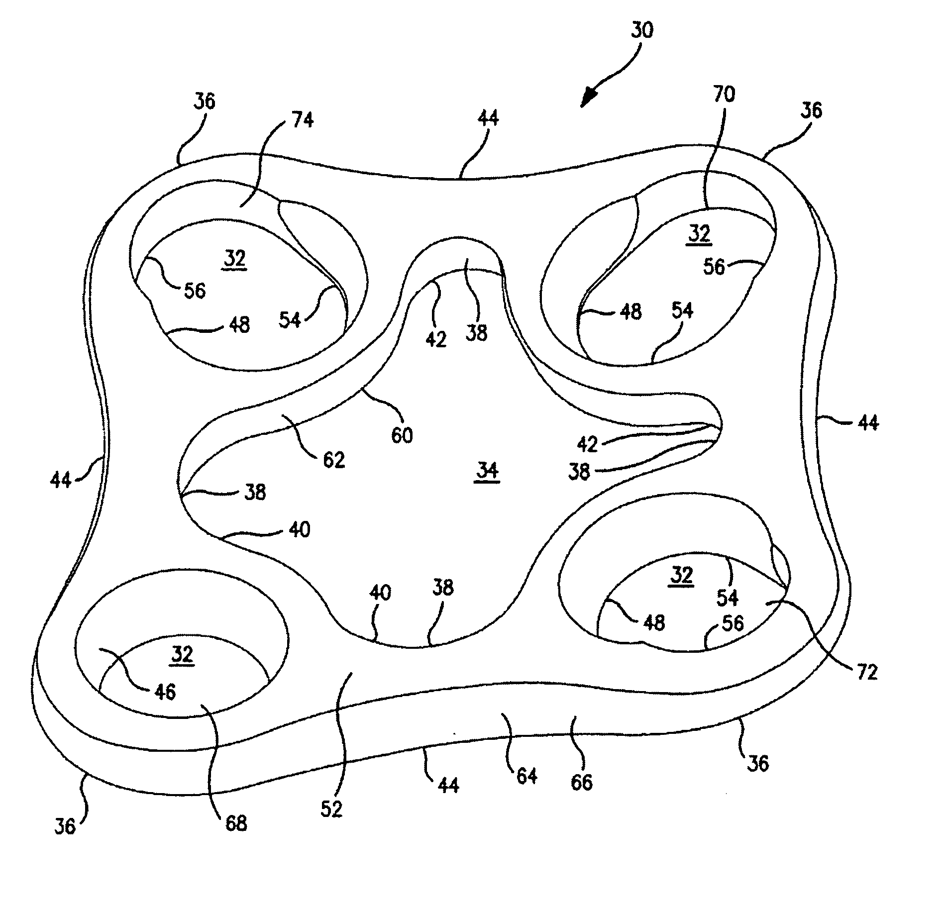
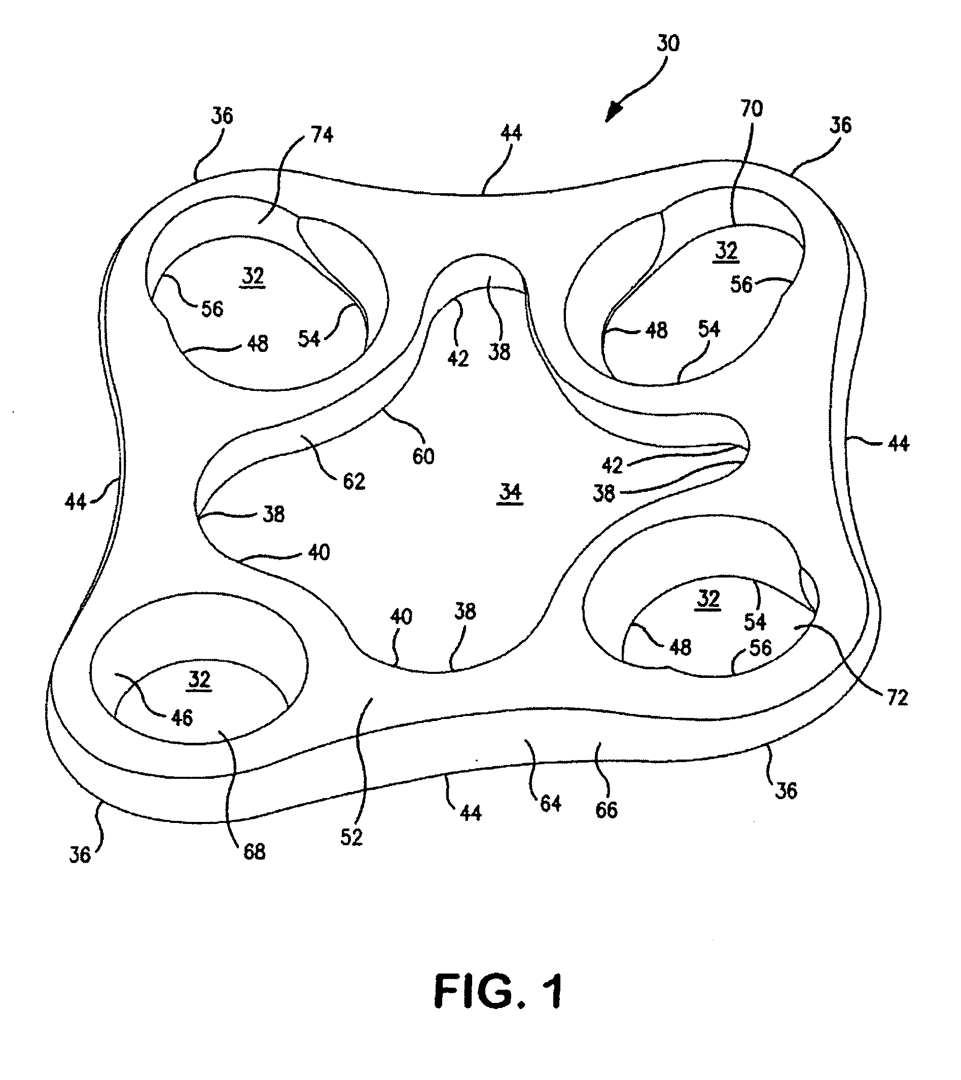
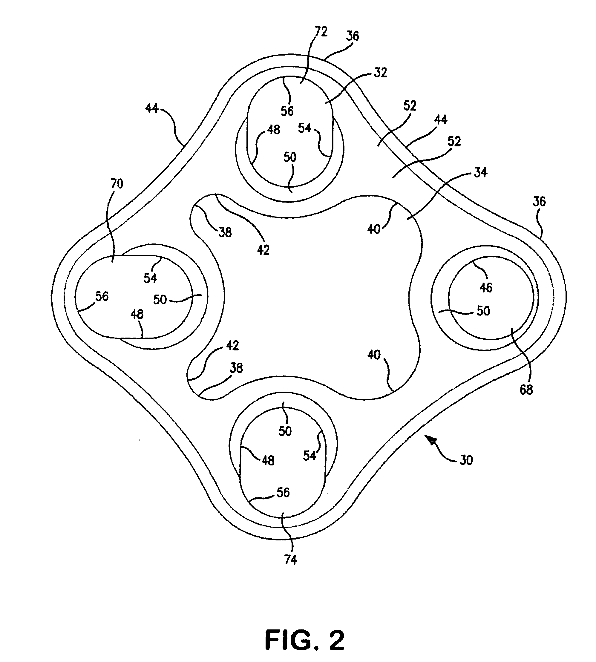
[0047] The carpal fusion plate 30 of the present invention is concave in profile to facilitate low profile implantation. Referring to FIGS. 1-3 and 6-12, the carpal fusion plate 30 in one embodiment may be generally diamond shaped and defines screw holes 32 and central opening 34. Screw holes 32 may be located generally at four corners 36 of fusion plate 30. Other shapes may be utilized in forming fusion plate 34 including but not limited to circular.

[0048] Referring to FIG. 2, central opening 34 may be multilobated and generally has four sides. Central opening 34 generally has four corners 38. Corners 38 of central opening 34 are generally located about midway between corners 36 of fusion plate 30. Central opening 34 includes two major lobes 40 and two minor lobes 42. The two major lobes 40 and two minor lobes 42 are located at adjacent corners.

[0049] Fusion plate 30 may be manufactured from implant grade 316L Stainless Steel. Other biocompatible materials such as titanium may al...


PUM


Abstract

A carpal fusion plate for use in fusion of the bones of the midcarpus or other bones. The fusion plate is concave and defines at least one round countersunk screw hole and at least one tapered elongate slotted aperture. The tapered elongate slotted aperture is narrower peripherally and broader centrally. The fusion plate also defines a multilobated central opening.

Description

FIELD OF THE INVENTION [0001] The invention relates to internal fixation devices utilized in orthopedic surgery. More particularly, the invention relates to an internal fixation device to be implanted within the body in direct contact with a bone or bone fragment to reinforce the bone or bone fragment during the healing process or for positioning a plurality of bones or bone fragments relative to one another. BACKGROUND [0002] Orthopedic fusion of damaged or degenerated bones in a joint is well known in the orthopedic arts. Joint fusion involves the fixing of several bones relative to one another so that they are no longer moveable relative to one another and so that they subsequently move as a unit. Typically joint fusion is accomplished by securing an appliance to the bones that are to be fused. Very often joint fusion involves the packing of bone graft material between the fixed bones to encourage the bones to grow together. A bone graft consists of fragments of bone removed from...

Claims


Application Information

Patent Timeline
17 Apr 2008
Publication
US20080091198A1
IPC
A61B17/58; A61B17/00; A61B17/56
CPC
A61B17/1686; A61B17/8004; A61B17/8061; A61B17/8605; A61B17/8625; A61B2019/462; A61B19/026; A61B2017/0046
Inventors
LEIBEL, DAVID A.; COONEY, WILLIAM P. III