
Targeted Marching

a target and marching technology, applied in the field of path finding, can solve problems such as the inability to find an optimal solution, and achieve the effect of ensuring the optimal solution

Active Publication Date: 2008-04-17
PHILIPS MEDICAL SYST TECH
View PDF16 Cites 112 Cited by
  • Summary
  • Abstract
  • Description
  • Claims
  • Application Information

AI Technical Summary

Benefits of technology

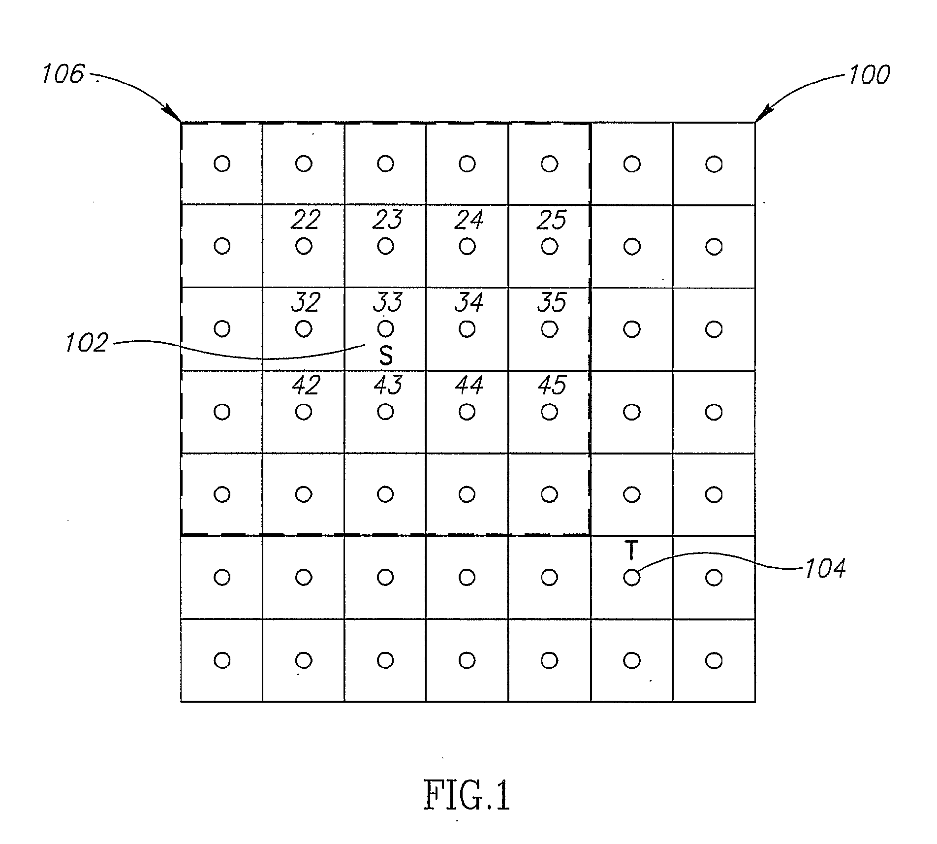
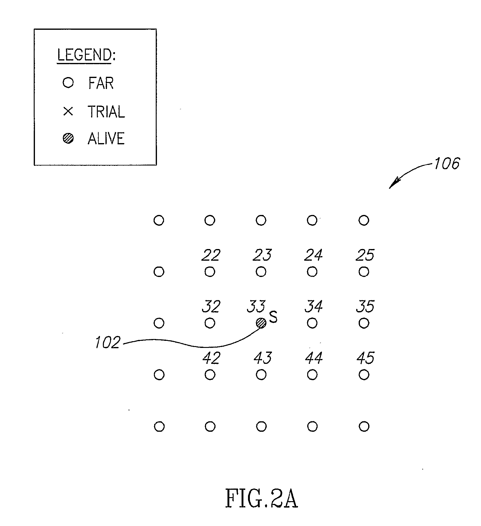
[0009]An aspect of some embodiments of the invention, relates to finding a path (path finding) from a start point to a target point in a continuous space, taking into account various constraints, and minimizing one or more cost function (cost criterion) of the path. In an exemplary embodiment of the invention, the path finding takes into account costs along the path, including a cost estimate of undecided parts of the path. In an exemplary embodiment of the invention, the resulting path is a smooth path. In an exemplary embodiment of the invention, the path is determined in a space of two or more dimensions, for example, three, four or more dimensions. In an exemplary embodiment of the invention, the actual path finding is performed on a discrete space, such that an approximation of an optimal or semi-optimal path in the original space is found. In an alternative embodiment, the path finding is carried out on a continuous space. In some embodiments, the continuous space is sampled as needed.
[0015]In some embodiments of the invention, the path is not constrained to pass through grid points. The found path is optionally not a simple path interconnecting grid points by straight lines and is not in the form of a straight line. In an exemplary embodiment of the invention, when the optimal path is not a straight line from S to T, the path found has a lower cost than a corresponding “best” path which is constrained to pass only through grid points.
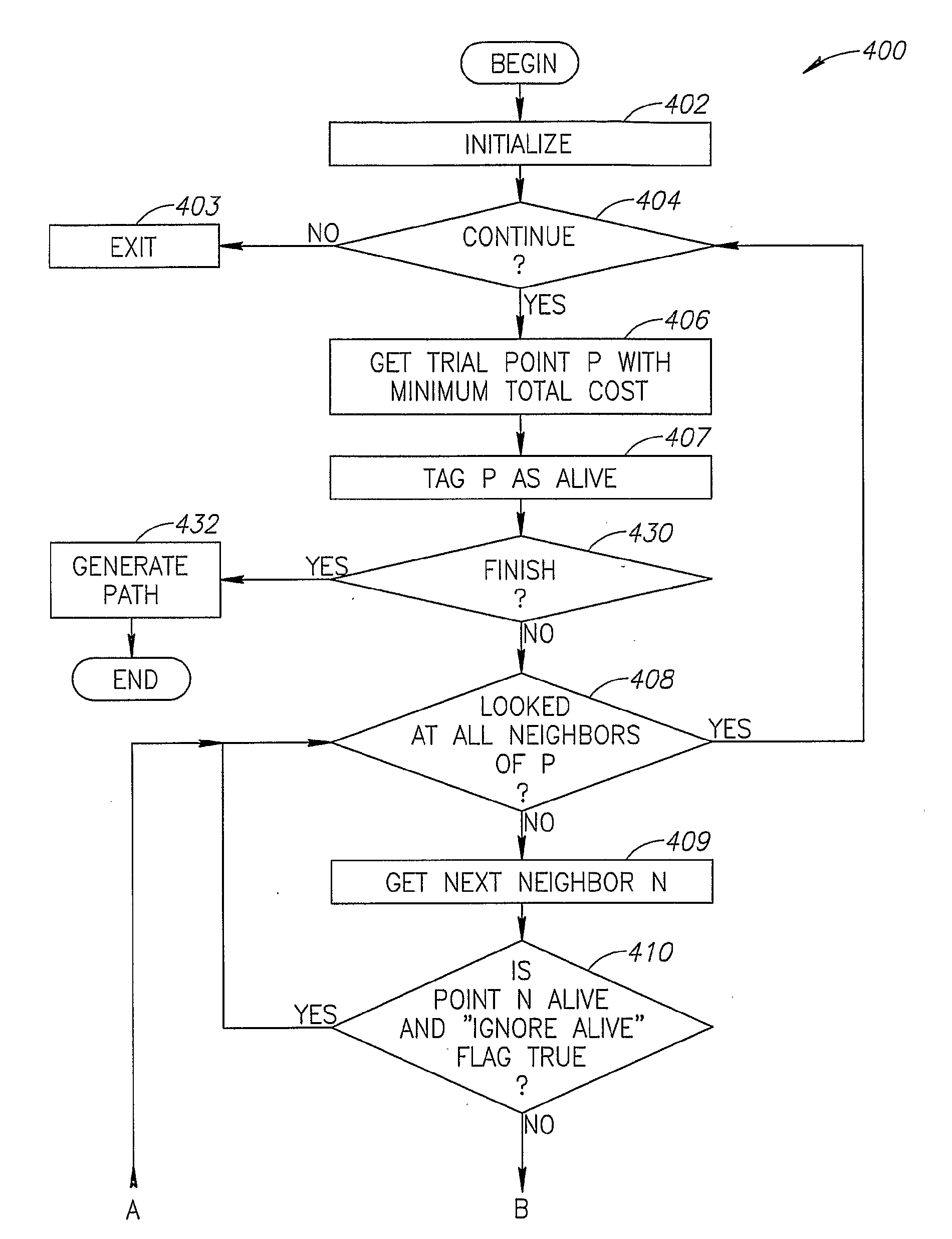
[0042]In an exemplary embodiment of the invention, a heap-type data structure is used for obtaining a point with the smallest cost.

Problems solved by technology

Thus, while the method may execute quickly, finding an optimal solution may not be guaranteed.

Method used


Image

  • Targeted Marching
  • Targeted Marching
  • Targeted Marching

Examples


Embodiment Construction

Overview

[0054]The invention, in some embodiments thereof, generally relates to finding a path from a start point to a target point, taking into account various constraints, and minimizing some objective function which defines the total cost of the path. In some embodiments of the invention, an optimal solution is not expected to be achieved. However, there may be a corresponding reduction in computational requirements.

[0055]Finding a minimum cost path has been employed in many applications, such as robotics, medical image processing, geographic information systems, and wire routing. For instance, path finding is carried out by a travel guidance system which computes the fastest route (path) from the present position S of a vehicle to a desired target destination T taking into account all alternative routes (paths) from S to T and various constraints, such as, traffic jams. The fastest route is found by minimizing the travel time (travel cost). In another, robotic navigation example,...


PUM


Abstract

A method of finding a path from a start point to a target point, in multi-dimensional space, including: (a) determining a plurality of points in a physical space, including a start point and an target point; (b) computing, using a cost function, for said points an accumulated path cost from the start point to a point; representing a minimal cost path from the start point to the point with respect to an optimization criteria; (c) computing for at least some of said points an estimated-cost-to-target from a point to the target point; and (d) after computing said costs, determining at least one of a minimal path or a minimal path cost of a path from the start point to the target point in the physical space, wherein the determination is based on said accumulated path costs, and is minimal with respect to the optimization criteria.

Description

RELATED APPLICATION[0001]The application claims the benefit under 119(e) of U.S. patent application Ser. No. 60 / 536,661 entitled “Vessel Centerline Determination”, filed on Jan. 15, 2004, the disclosure of which is incorporated herein by reference. This application is also related to a PCT application entitled “Vessel Centerline Determination”, having attorney's docket number 032 / 04081, being filed on same date in the Israel Patent Office, the disclosure of which is incorporated herein by reference.FIELD OF THE INVENTION[0002]The present invention relates to path finding and / or to calculating path costs, for example in physical and in computer applications.BACKGROUND OF THE INVENTION[0003]Path planning or path finding methods are used in many applications, for instance, in robotics, computer games, graphics, vision and imaging. Various path planning or path finding methods have been reported in the art, in particular A*, and Fast-marching methods. Shortest path algorithms on graphs,...

Claims


Application Information

Patent Timeline
IPC IPC(8): G01C21/00G06T5/00G06T7/60G06T17/05G06T17/40
CPCG06T7/0083G06T7/604G06T2207/10081G06T2207/20044A61B6/506G06T2207/20136G06T2207/30101G06T2210/41G06T2207/20101G06T7/12G06T7/64G06T7/181
Inventor MILSTEIN, IDOAKERMAN, SHMUELMILLER, GAD
Owner PHILIPS MEDICAL SYST TECH
Learn More