Ice maker with ice bin level control

a level control and ice maker technology, applied in the field of ice production, can solve the problems of melting the ice stored in the ice maker, ice cubes that cannot be sprayed, and ice to spill out of the ice maker

Inactive Publication Date: 2008-04-24
U LINE CORP A WI CORP
View PDF44 Cites 22 Cited by
  • Summary
  • Abstract
  • Description
  • Claims
  • Application Information

AI Technical Summary

Benefits of technology

[0017]In another aspect, the present invention provides a clear ice maker unit with a cabinet defining an ice maker chamber and an ice storage bin. The ice maker includes a clear ice maker mechanism disposed in the ice maker chamber and capable of cascading water over a vertically disposed evaporator during a plurality of ice making cycles, each ice making cycle resulting in the production of a quantity of clear ice. A controller is configured to control the clear ice maker, t

Problems solved by technology

Such an approach results in clouded ice cubes resulting from air and impurities present within the frozen water.
Overfilling the ice bin can cause ice to spill out of the ice maker when the ice maker door is opened.
Overfilling the ice bin can also lead to ice building up in the ice making assembly which can result in water traveling down the bui

Method used


Image

  • Ice maker with ice bin level control
  • Ice maker with ice bin level control
  • Ice maker with ice bin level control

Examples


Embodiment Construction

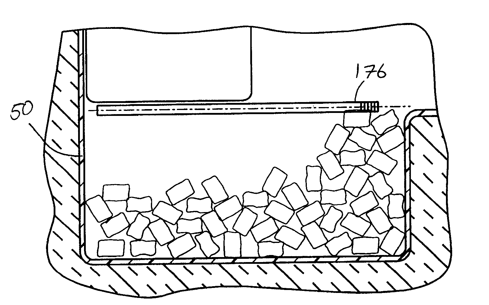
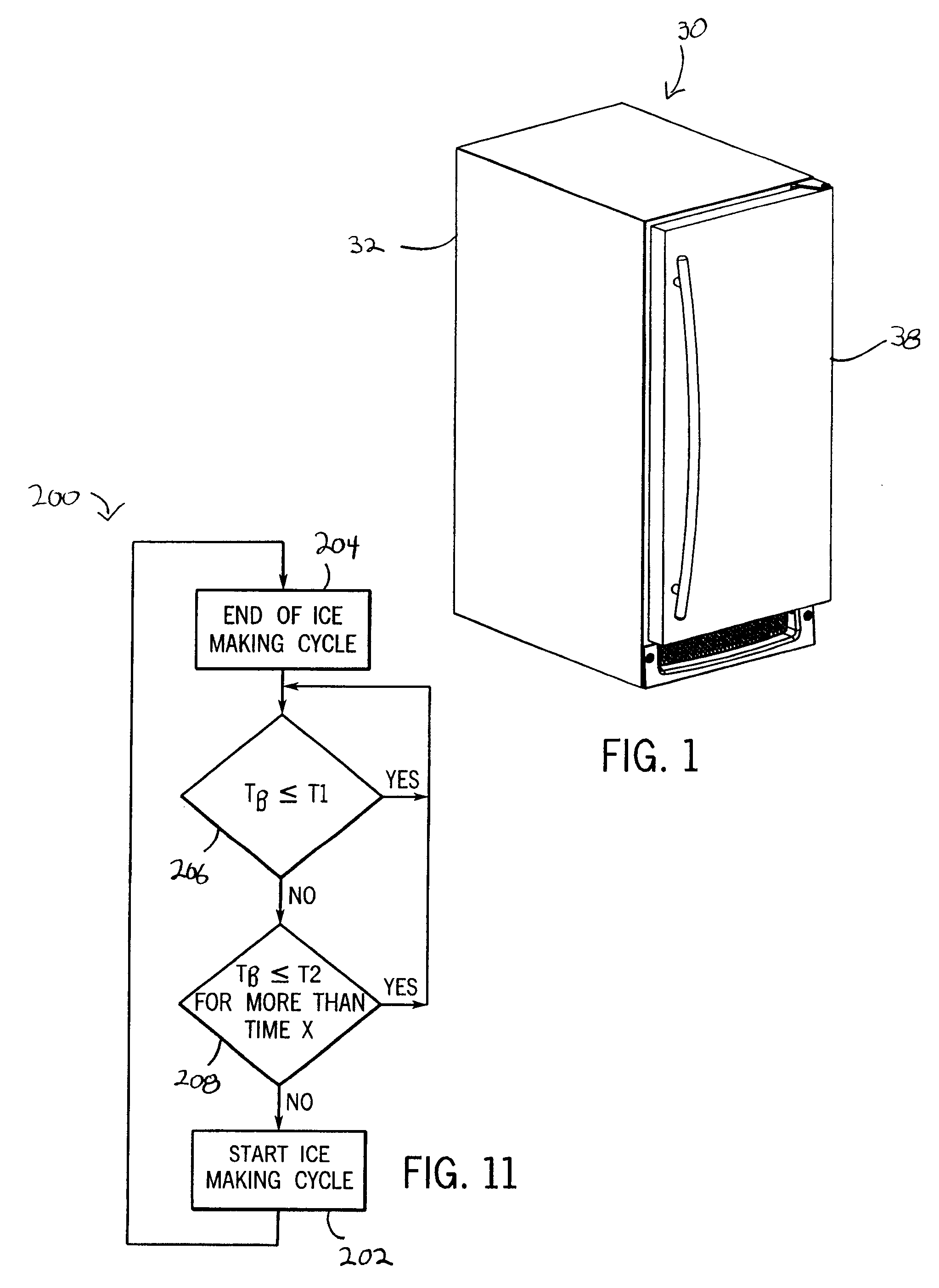
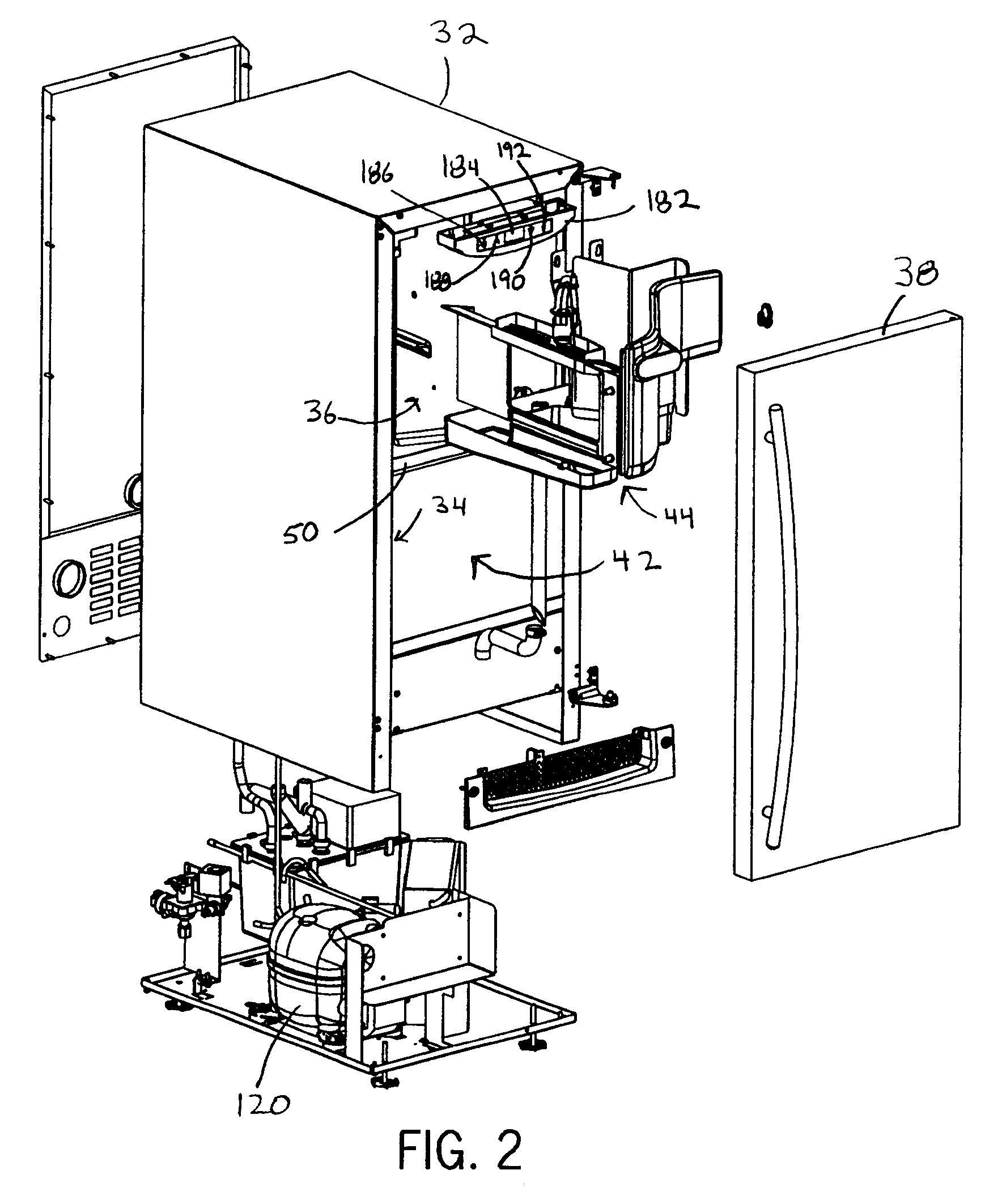
[0040]Referring to FIGS. 1-2, a clear ice maker 30 includes a cabinet 32 with an upper forward opening 34 and an interior 36. The opening 34 is closed by a door 38 that is hinged to the cabinet 32. The interior 36 includes an ice making area 40 in the upper portion of the cabinet 32 and a bin area 42 below the ice making area 40. The ice making area 40 includes a clear ice maker assembly 44. As discussed below, the clear ice maker assembly 44 is electrically connected to a controller 46 and connected to a refrigeration system 48. The bin area 42 includes a rectangular ice bin 50. The bin area 42 and ice in the ice bin 50 are not cooled by the refrigeration system 48. Both the cabinet 32 and the door 38 are formed of inner molded plastic members and outer formed metal members with the space filled with an insulating layer of foam material, all of which is well known in the art. Thus, ice in the ice bin 50 is insulated from the ambient air.

[0041]Referring now to FIGS. 2-5, the clear i...


PUM


Abstract

A clear ice maker unit has a clear ice maker mechanism with a cascading water evaporator configured to make clear ice during ice making cycles. A controller uses fuzzy logic to control the clear ice maker and determine whether to initiate a next ice making cycle based on input signals from a thermistor in the ice storage bin. The controller will prevent initiation of an ice making cycle when the ice bin is at or below a threshold temperature. The controller will also prohibit ice making when the ice bin is at or below a second, slightly higher temperature for more than a prescribed period of time. In this way, the clear ice maker can recognize an uneven distribution of ice and maintain an optimal amount of ice in the bin.

Description

CROSS-REFERENCE TO RELATED APPLICATIONS[0001]This application claims the benefit of U.S. Provisional patent application Ser. No. 60 / 862,340 filed on Oct. 20, 2006, and entitled “Ice Maker with Ice Bin Level Control,” hereby incorporated by reference as if fully set forth herein.STATEMENT REGARDING FEDERALLY SPONSORED RESEARCH[0002]Not applicable.BACKGROUND OF THE INVENTION[0003]The present invention relates to the manufacture of ice, and particularly to automated clear ice maker units.[0004]A conventional ice maker forms ice cubes by depositing water in a mold attached to an evaporator and allowing the water to freeze in a sedentary state. Such an approach results in clouded ice cubes resulting from air and impurities present within the frozen water.[0005]It is also known to form ice by flowing water over a freezing surface to allow the air and impurities to separate from the water before freezing layer-by-layer to form the ice cube. This eliminates the clouding associated with sede...

Claims


Application Information

Patent Timeline
IPC IPC(8): F25C1/12
CPCF25C1/12F25C2600/04F25C5/187
Inventor DOBERSTEIN, ANDREW J.RAND, THOMAS W.
Owner U LINE CORP A WI CORP
Why Eureka
Try Eureka