

Process for upgrading hydrocarbon feedstocks using solid adsorbent and membrane separation of treated product stream
- Summary
- Abstract
- Description
- Claims
- Application Information
AI Technical Summary
Benefits of technology
Problems solved by technology
Method used
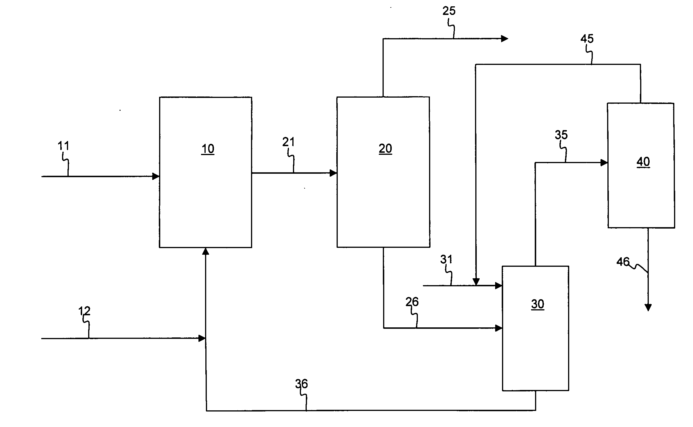
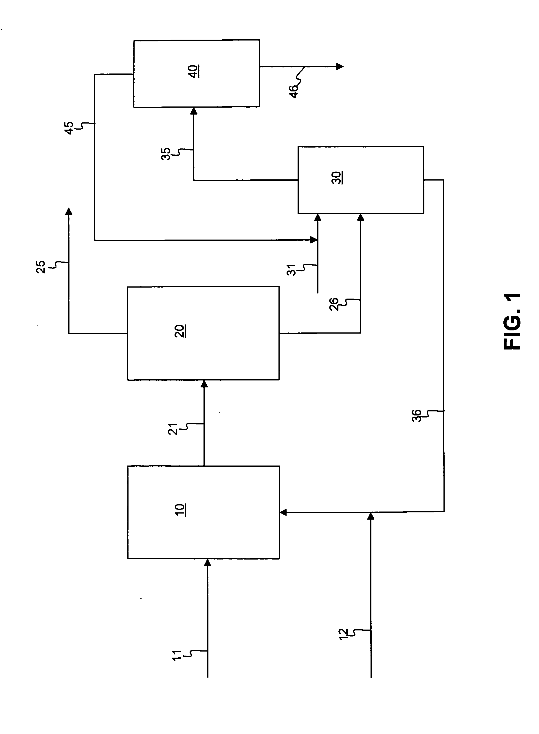
Image

Examples
example 1
[0046]A slurry was formed with 50 g of silica and 200 g of light diesel oil, i.e., 1:4 adsorbent to oil ratio. The light diesel oil had an API gravity of 37.4 degrees, an ASTM D86 distillation curve of 201 / 229 / 235 / 258 / 275 / 295 / 328 / 348 / 354 at IBP / 5 W % / 10 W % / 30 W % / 50 W % / 70 W % / 90 W % / 95 W % / FBP, respectively, and contained 1.0 W % sulfur, and 42 ppmw nitrogen. The silica gel adsorbent had a 100-200 mesh size. The slurry was mixed with a magnetic stirrer at a rate of 60 RPM at 20° C. and atmospheric pressure for 30 minutes. The sulfur components present before and after the process of adsorption followed by membrane filtration are set forth in Table 1 below.
[0047]The hydrocarbon-solid adsorbent was transferred to a membrane filtration device with vacuum pressure applied, using a membrane having pores of 4-5 microns, for separation. The total diesel recovered was 164 g, or about 80 W %, after two minutes, and the total sulfur content was reduced by 40 W %. The remaining adsorbent was...
example 2
[0049]A hydrotreated diesel containing 1009 ppmw of sulfur was subjected to membrane-adsorption desulfurization in a two-stage process. A slurry was formed as in Example 1, with 51 g of silica gel having 100-200 mesh size and 205 g of light diesel oil. The slurry was mixed with a magnetic stirrer at a rate of 60 RPM at 20° C. and atmospheric pressure for 30 minutes. The hydrocarbon-solid adsorbent slurry was transferred and the components separated in a membrane filtration device with vacuum pressure applied, using a membrane having pores of 4-5 microns. The total diesel recovered after two minutes was 163 g, about 80W %. The remaining adsorbent was washed further with an equivalent volume of pentane, and the total oil recovery was 99.0 W % after pentane evaporation. This completed the first stage.
[0050]In the second stage of the two-stage process, 158 g of the recovered diesel from the first stage was used to form a second slurry with 40 g of fresh silica adsorbent. The slurry was ...
example 3
[0051]A hydrotreated diesel containing 1009 ppmw of sulfur was subjected to membrane-adsorption desulfurization in a three-stage process. A slurry was formed as in Example 1, with 51 g of silica gel having 100-200 mesh size and 205 g of light diesel oil. The slurry was mixed with a magnetic stirrer at a rate of 60 RPM at 20° C. and atmospheric pressure for 30 minutes. The hydrocarbon-solid adsorbent slurry was transferred and the components separated in a membrane filtration device with vacuum pressure applied, using a membrane having pores of 4-5 microns. The total upgraded diesel recovered after two minutes was about 80 W %. The remaining adsorbent was washed further with an equivalent volume of pentane, and the total oil recovery was 99.0 W % after pentane evaporation. This completed the first stage.
[0052]In the second stage of the three-stage process, 158 g of the recovered diesel from the first stage was used to form a second slurry with 40 g of fresh silica adsorbent. The slur...
PUM
| Property | Measurement | Unit |
|---|---|---|
| Temperature | aaaaa | aaaaa |
| Temperature | aaaaa | aaaaa |
| Angle | aaaaa | aaaaa |
Abstract
Description
Claims
Application Information