Thermal load locator

a technology of load locator and thermal load, which is applied in the direction of lighting and heating apparatus, instruments, and domestic cooling apparatus, etc., can solve the problems of increasing the density of the amount, becoming increasingly difficult to remove the heat, and conventional room air conditioning

Inactive Publication Date: 2008-04-24
LIEBERT
View PDF23 Cites 25 Cited by
  • Summary
  • Abstract
  • Description
  • Claims
  • Application Information

AI Technical Summary

Problems solved by technology

Because advances in technology have lead to an increased density of the amount of electronic equipment that can be provided in a set amount of space, it has become increasingly difficult to remove this heat by means of the conventional room air conditioning sized according to traditional practices.
General purpose cooling systems for rooms and open spaces now are either oversized and inefficient to handle the additional cooling requirements or inadequate for single racks of critical electronic

Method used


Image

  • Thermal load locator
  • Thermal load locator
  • Thermal load locator

Examples


Embodiment Construction

[0018]The Figures described above and the written description of specific structures and processes below are not presented to limit the scope of what Applicants have invented or the scope of protection for those inventions. Rather, the Figures and written description are provided to teach any person skilled in the art to make and use the inventions for which patent protection is sought. Those skilled in the art will appreciate that not all features of a commercial implementation of the inventions are described or shown for the sake of clarity and understanding. Persons of skill in this art also appreciate that the development of an actual commercial embodiment incorporating aspects of the present inventions will require numerous implementation-specific decisions to achieve the developer's ultimate goal for the commercial embodiment. Such implementation-specific decisions may include, and likely are not limited to, compliance with system-related, business-related, government-related ...


PUM


Abstract

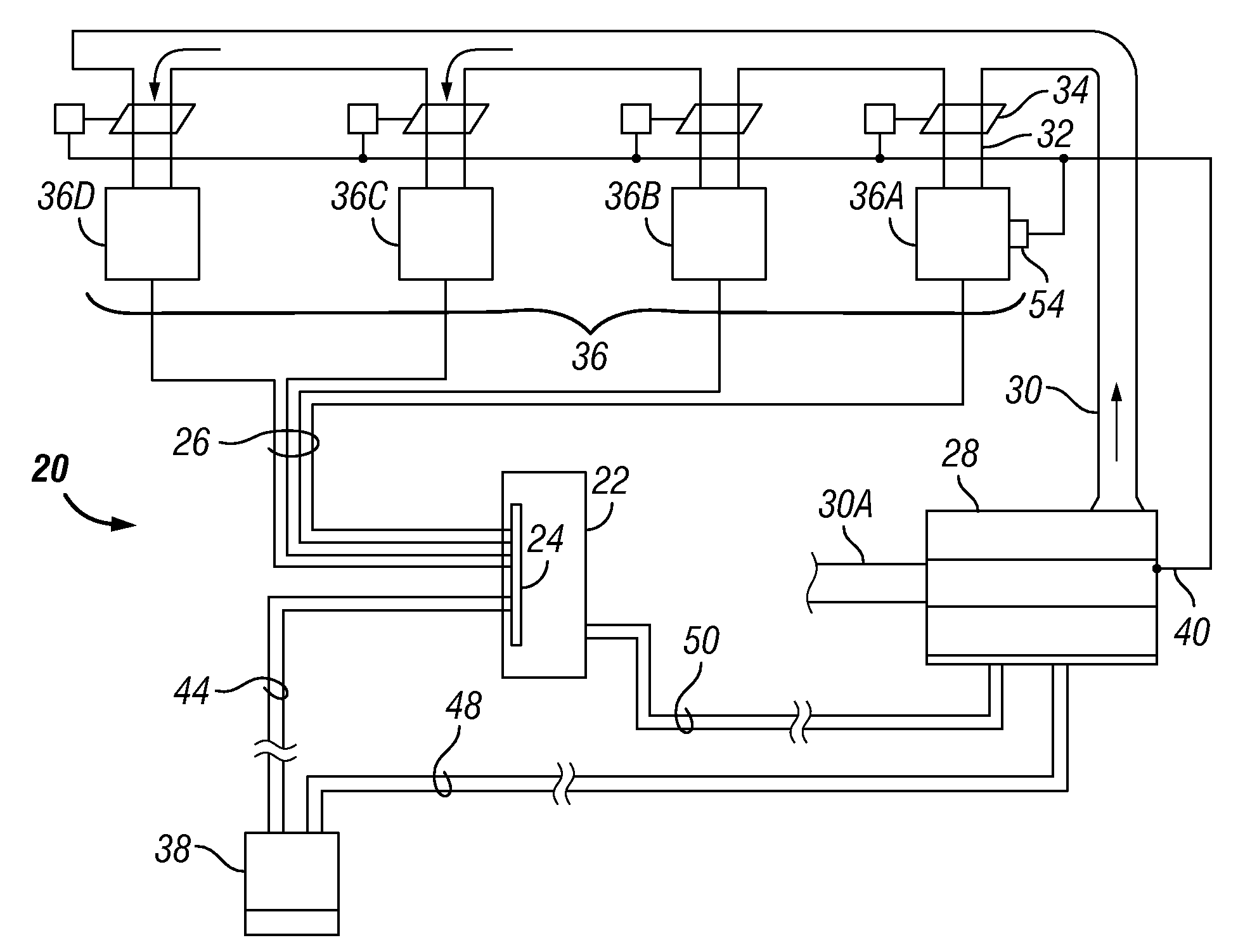
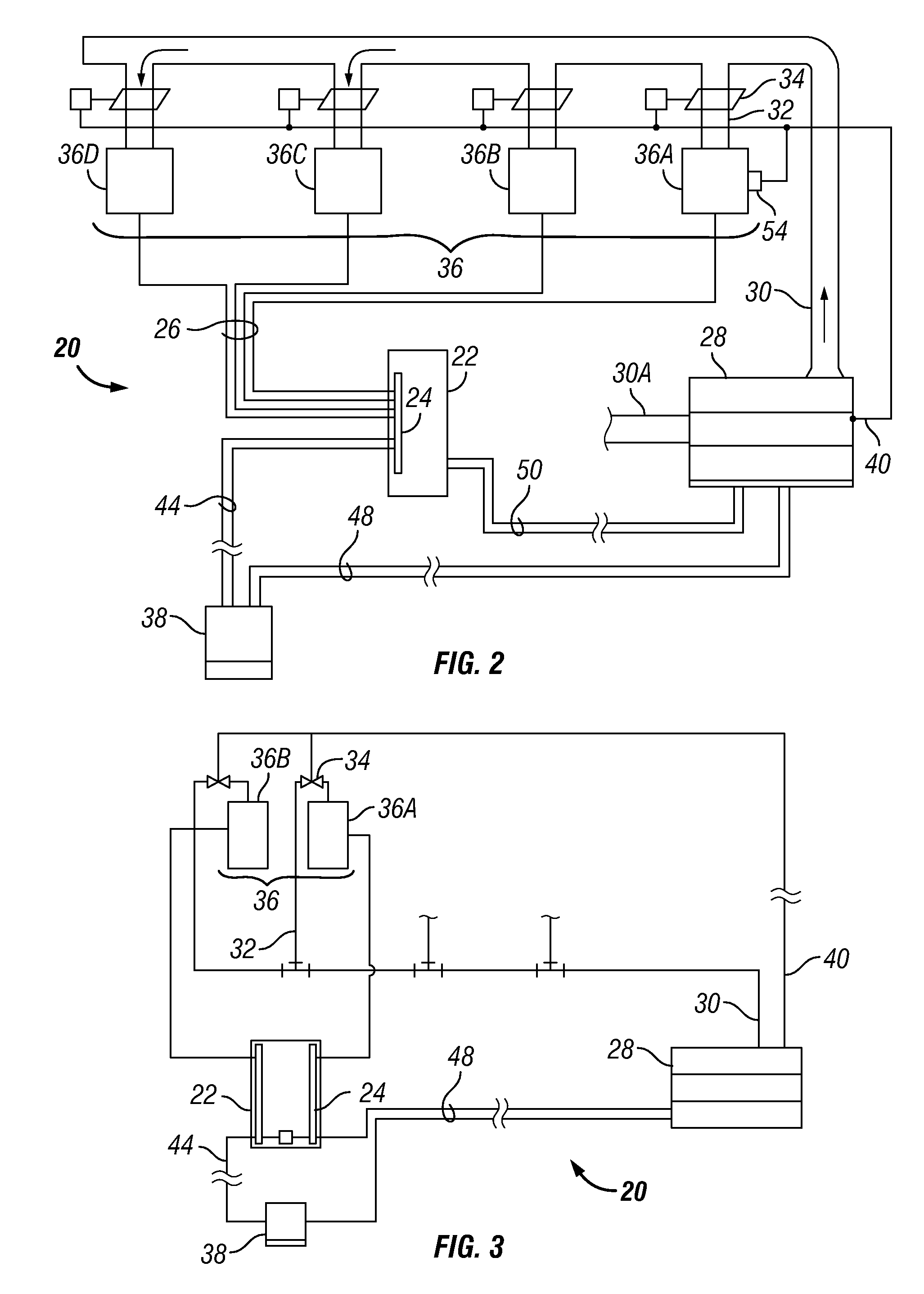
A centralized cooling system can selectively deliver individualized cooling to individual electrical load units. The system can provide direct cooling from a manifold of cooling outlets in a controlled manner based on the sensed electrical loads of particular load units. A branch monitoring system monitors the load on electrical feeds that are coupled to electrical load units. A controller is coupled to the branch monitoring system and provides output to control a cooling unit. At least one control valve is further coupled to the controller downstream of the cooling unit generally at each cooling outlet to control an amount of cooling fluid, such as air or liquid, directed to one or more of the units. If a load changes for a given unit, the controller can actuate a cooling valve coupled to a corresponding cooling outlet and alter the amount of cooling fluid flowing into or around the unit(s).

Description

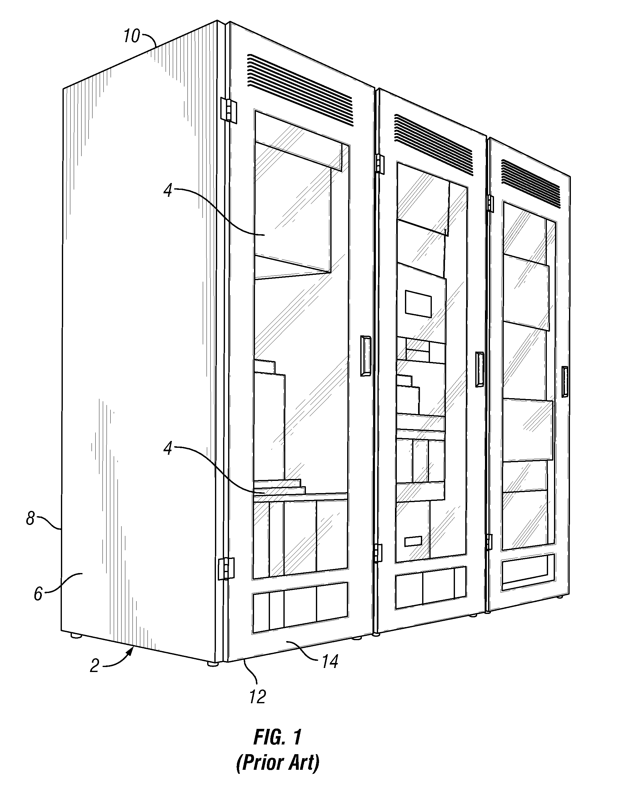
CROSS REFERENCE TO RELATED APPLICATIONS[0001]This application claims the benefit of U.S. Provisional Appl. No. 60 / 862,538, filed Oct. 23, 2006, and is incorporated herein by reference.STATEMENT REGARDING FEDERALLY SPONSORED RESEARCH OR DEVELOPMENT[0002]Not applicable.REFERENCE TO APPENDIX[0003]Not applicable.BACKGROUND OF THE INVENTION[0004]1. Field of the Invention.[0005]The present invention relates generally to electronic equipment cabinets and housings, and, more particularly to electronic equipment cabinets having cooling systems.[0006]2. Description of the Related Art.[0007]With the expansion of telecommunication and computer technology, increasing amounts of electronic equipment are required at businesses and other facilities. Large amounts of electronic equipment are often stored in a room devoted to that purpose. As shown in FIG. 1, the equipment is generally organized in a cabinet 2 of standard dimensions with multiple horizontal trays 4 to support multiple rows of equipme...

Claims


Application Information

Patent Timeline
IPC IPC(8): F25D23/12F25D17/02
CPCG06F1/206H05K7/20836H05K7/20781G06F2200/201
Inventor MARTIN, JAMES K.
Owner LIEBERT
Why Eureka
Try Eureka