
Transport Packaging Testing Device

a testing device and packaging technology, applied in the direction of vibration testing, mechanical vibration separation, structural/machine measurement, etc., can solve the problems of increasing the size and weight of the device, requiring special testing places for large and heavy devices, and increasing the cost of the device, so as to achieve the effect of hardly restricting the testing place, high accuracy of vibration test data in respective longitudinal, lateral and vertical directions

Inactive Publication Date: 2008-04-24
MIZUGUCHI SHINJI
View PDF10 Cites 5 Cited by
  • Summary
  • Abstract
  • Description
  • Claims
  • Application Information

AI Technical Summary

Benefits of technology

[0013] Accordingly, it is an object of the present invention to provide: firstly, a transport packaging testing device that allows a triaxial simultaneous vibration test in respective longitudinal, lateral, and vertical directions, namely, in Y-, X-, and Z-axis directions, is compact, lightweight, and inexpensive, hardly limits testing places, and enables test installation of lightweight test objects; secondly, a transport packaging testing device wherein the accuracy of vibration test data in respective longitudinal, lateral, and vertical directions is high; thirdly, a transport packaging testing device that allows a triaxial simultaneous vibration test in respective longitudinal, lateral, and vertical directions, namely, in Y-, X-, and Z-axis directions, is compact, lightweight, and inexpensive, hardly limits testing places, and enables test installation of a wide range of test objects including lightweight objects and heavyweight objects; fourthly, a transport packaging testing device wherein the accuracy of vibration test data in respective longitudinal, lateral, and vertical directions is high; and fifthly, a transport packaging testing device wherein vibration test data according to an actual vehicle test can be simulatively obtained.
[0022] The vibration table may have a square shape, a rectangular shape, or a circular shape in plan view, and is not limited as long as a table surface on which test objects can be placed is provided. The holding fixture may hold a test object fixedly or in a freely moving state. The coil springs support the vibration table and the test object or the like held on a bed of the vibration table, and reduce or absorb vibration of the bed to minimize or prevent transmission of the vibration to the stand. The table surface and / or the holding fixture of the vibration table may be electrostatically treated by attaching an electrostatic sheet to a surface in contact with test objects, or the like so that a static electricity is hardly generated between the table surface and / or the holding fixture, and the test objects in process of testing.
[0032] Furthermore, the transport packaging testing device according to the first embodiment is compact, lightweight, and inexpensive, and testing places are hardly limited as long as space for the stand is given.
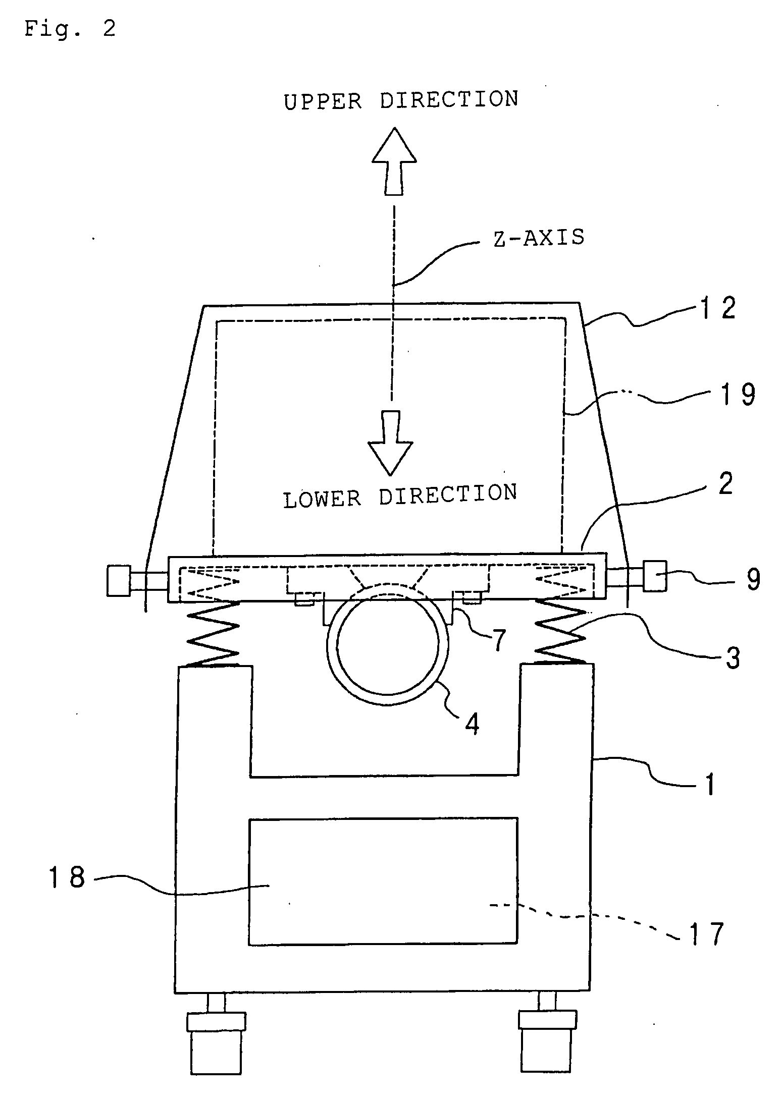
[0036] While the vibration of the vibration table is absorbed into the coil springs so as to be prevented from being transmitted to the stand, the triaxial simultaneous vibration test can be conducted by simultaneously vibrating a test object on the vibration table in the respective longitudinal, lateral, and vertical directions.
[0038] The transport packaging testing device according to the second embodiment is compact, lightweight, and inexpensive, and testing places are hardly limited as long as space for the stand is given.
[0040] Preferably, the front and rear eccentric flywheel built-in parts of the central vibrator, and the right and left vibrators are suspended on the back side of the vibration table in an axially symmetrical manner with respect to the center axis of the vibration table, thereby keeping center-of-gravity balance, i.e., horizontal balance of the vibration table. Therefore, accuracy of vibration test data in the respective longitudinal, lateral, and vertical directions may be increased.

Problems solved by technology

For that reason, increases in size and weight of the device are unavoidable, and foundation work or anchoring driving work is required in an installation site.
Thus, the device becomes expensive.
Furthermore, there is a problem that such large and heavy device requires a special testing place.
In this case, adjacent transport packages may rub together to be damaged, or articles may rub against packages to be damaged, and a commercial value may be lost.
However, the former has the above-described problems, and the latter has problems such that test results vary according to transport environment conditions such as driving manners, much labor and cost is required, data is difficult to obtain in process of testing, and risks are increased.
Such increases in strength result in increases in weight of the vibration table and the holding fixture.

Method used


Image

  • Transport Packaging Testing Device
  • Transport Packaging Testing Device
  • Transport Packaging Testing Device

Examples


first embodiment

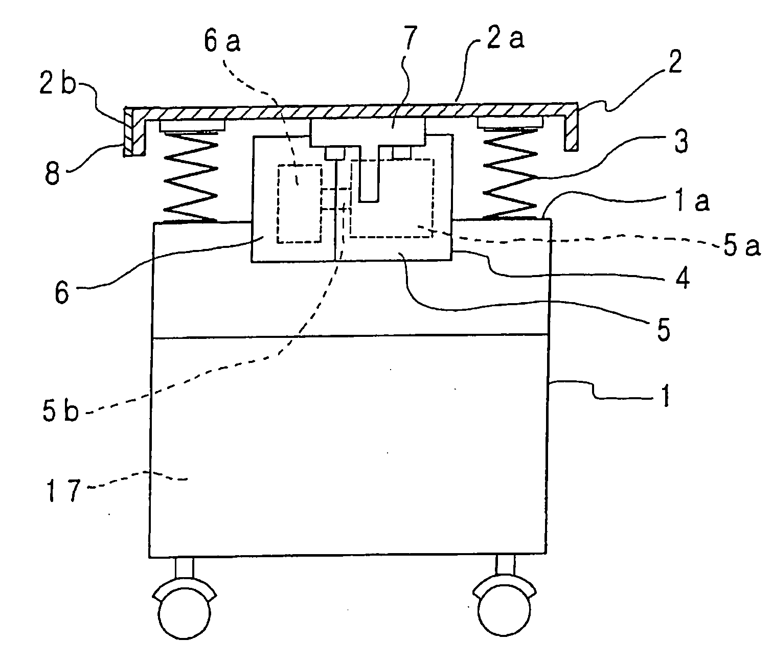
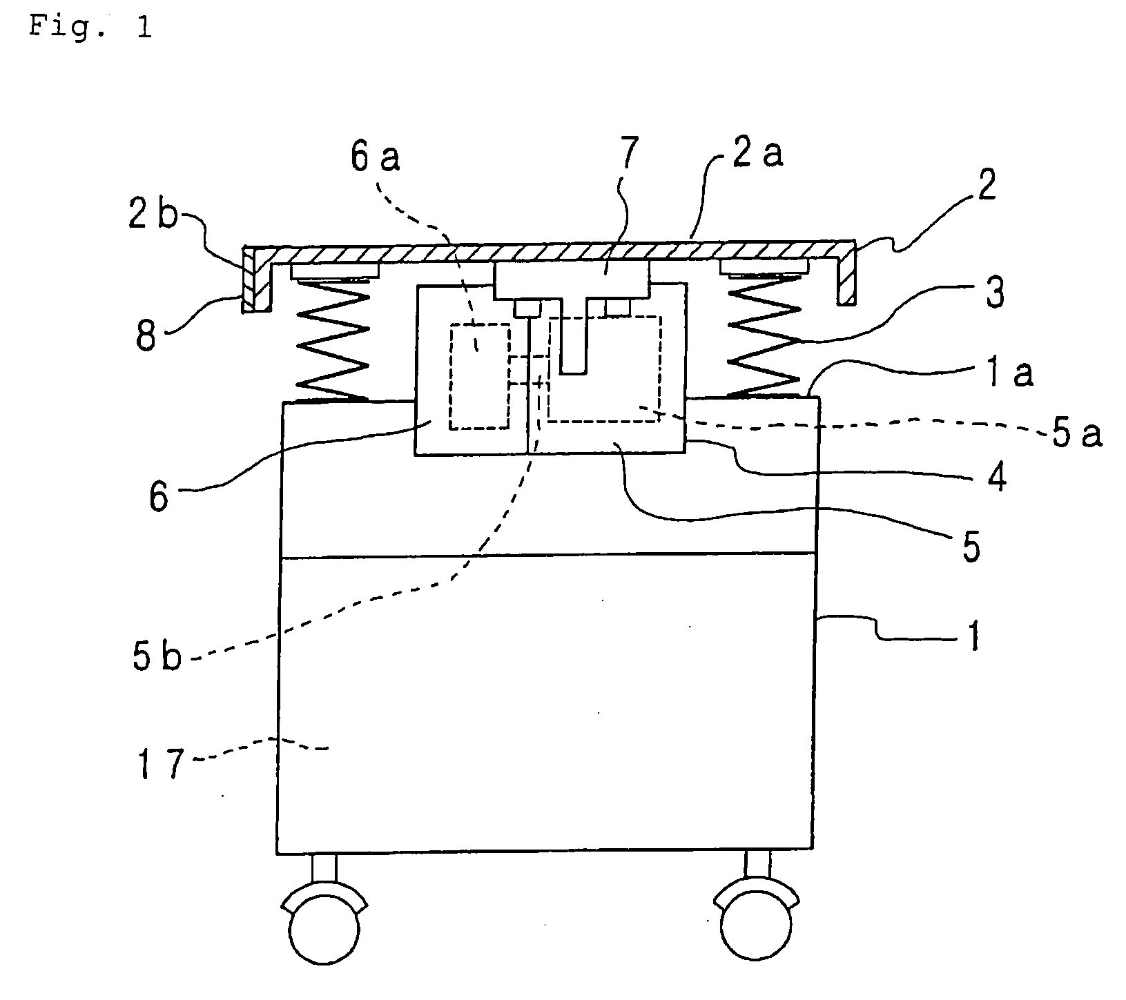
[0053] FIGS. 1 to 5 show a transport packaging testing device according to the present invention. A stand 1 horizontally supports a vibration table 2 on an upper face 1a thereof through coil springs 3 provided at four corners of the back side of the vibration table 2. Thus, vibration of the vibration table 2 produced by a vibrator 4 provided on the back side of a bed is absorbed into the coil springs 3 so as to be substantially prevented from being transmitted to the stand 1.

[0054] The vibrator 4 includes a rotation drive built-in part 5 and an eccentric flywheel built-in part 6, and is configured to produce vibration of a frequency corresponding to the rotation speed due to unbalanced weight between a rotary shaft 5b of a rotation drive 5a with a horizontal rotational axis and an eccentric flywheel 6a integrally interlocking with the rotary shaft 5b. The rotation drive 5a is adapted to receive signals from a vibrator control part 17 provided in the stand 1 to be normally and revers...

second embodiment

[0065] FIGS. 6 to 10 show a transport packaging testing device according to the present invention. A stand 30 is provided with casters 31 with locks at four corners of the bottom face thereof, and vertically movable and adjustable fixing legs 32 at the sides of the respective casters 31, and is configured to easily move and easily stop at an arbitrary position.

[0066] On an upper face 30a of the stand 30, a vibration table 33 is horizontally supported through coil springs 34 provided at four corners of the back side of the vibration table 33. Thus, vibration of the vibration table 33 caused by operation of a central vibrator 35 and a pair of right and left vibrators 36 suspended on the back side of the stand 30 is absorbed into the coil springs 34 so as to be prevented from being transmitted to the stand 30. A vibration sensor 33e is provided on the back side of the vibration table 33, for detecting respective vibrations in the vertical direction (Z-axis direction), lateral direction...


PUM


Abstract

A transport packaging testing device includes a vibration table horizontally supported on a stand through coil springs provided at four corners of the back side of the vibration table; a table surface provided on an upper face of the vibration table that holds a test object thereon with a holding fixture; a vibrator provided on the back side of the vibration table for producing vibration of a frequency corresponding to rotation speed due to unbalanced weight between a rotary shaft of a rotation drive with a longitudinally-horizontal rotational axis and an eccentric flywheel integrally interlocking with the rotary shaft; a mounting leg mounted and suspended toward a rotation drive built-in part of the vibrator; and a vibrator control part that controls normal and reverse rotation of the rotation drive. Based on the longitudinal, lateral, and vertical vibrations by the vibrator, the vibration table is subjected to triaxial simultaneous vibration.

Description

BACKGROUND OF THE INVENTION [0001] 1. Field of the Invention [0002] The present invention relates to a transport packaging testing device that is useful for testing by simulative reproduction of vibration received by various types of articles or packages of different weights including lightweight objects and heavyweight objects in various transport or usage environments. [0003] 2. Description of the Related Art [0004] Japanese Unexamined Patent Application Publication No. 2005-91080 discloses a vibration testing device wherein a vibration table 4 is vibrated in two or three dimensions, only in X direction (lateral direction), Y direction (longitudinal direction), or Z direction (vertical direction), and a test object on the vibration table 4 is vibrated, thereby conducting a test. [0005] Also, dedicated vibration generators are provided for obtaining vibrations in the respective Y, X, Z directions, namely, three vibration generators are required. [0006] For that reason, increases in...

Claims


Application Information

Patent Timeline
IPC IPC(8): G01M7/02
CPCG01M7/06G01M7/04G01M7/022G01M7/027G01N2203/0058
Inventor MIZUGUCHI, SHINJI
Owner MIZUGUCHI SHINJI
Learn More