Rotary Bag Machine With Skirtless Seal

a bag machine and seal technology, applied in the field of bag making machines, can solve the problems of waste of web between seals, difficult in practice, and difficult in practi

Inactive Publication Date: 2008-04-24
CMD CORP
View PDF33 Cites 8 Cited by
  • Summary
  • Abstract
  • Description
  • Claims
  • Application Information

AI Technical Summary

Problems solved by technology

Ideally, the perforation is close to the seal to reduce waste, although this is difficult in practice.
The web between the pair of seals is wasted.
Thus, the pair of seals should be close to one another to reduce waste, although this is also difficult in practice.
Sensing the seal has proven to be difficult.
If the perforation is placed too close to one side seal, then the seal may be cut off, rendering the bag useless.
Because sensing the seal is difficult, much waste is generated in bag making, or bags are ruined.
The wasted web, (i.e. the web between a seal and the adjacent perforation), or the web used to make the ruined bag, can be very costly, particularly for high speed bag machines where the number of bags made per hour is great.
Another problem of prior art machines is that perforations may be skewed with respect to the seals, because the perforations are created downstream, and the web can wander or stretch.
Generally, sharp mechanical knives cannot be adjusted to change the perforation strength, and they can be costly, complex, and difficult to use.
Other type of bag machines, such as intermittent motion machines (not rotary drum machines) use burn off seals to seal and cut or perforate at the same time but speed is limited to about 300 fpm due to the reciprocating motion, dwell time, and difficulty handling the loose bags.
Generally, intermittent motion machines are not as fast as rotary drum continuous machines, and thus produce far fewer bags per machine hour.

Method used


Image

  • Rotary Bag Machine With Skirtless Seal
  • Rotary Bag Machine With Skirtless Seal
  • Rotary Bag Machine With Skirtless Seal

Examples


Embodiment Construction

[0073] While the present invention will be illustrated with reference to a particular bag machine, it should be understood at the outset that the invention can also be implemented with other machines, and using other components. Bag machine, as used herein, includes a machine used to make bags such as draw tape bags, non-draw tape bags, and other bags. Any input section (unwinds and dancers, e.g.) and any output section (winders, folders, e.g.) may be used with the present invention. Bags may be comprised of traditional poly material, other materials such as starch, polyactic acid (PLA), cellulose, polyhydroxy alkanoates (PHA), and lignin, and / or be biodegradable, compostable, etc., such as Mater-Bi®, Ecoflex®, Ecovio®, Bioplast GF106®

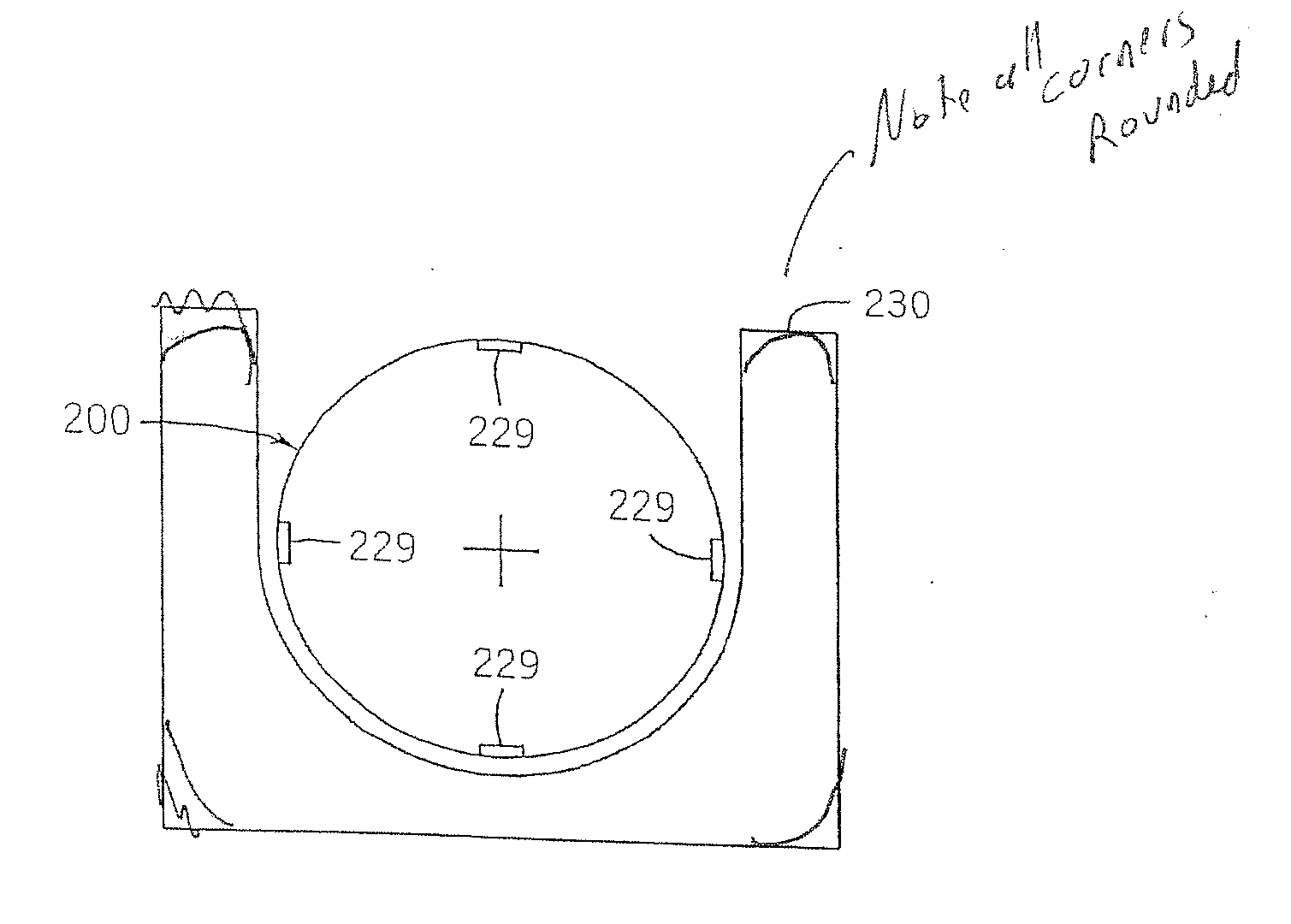
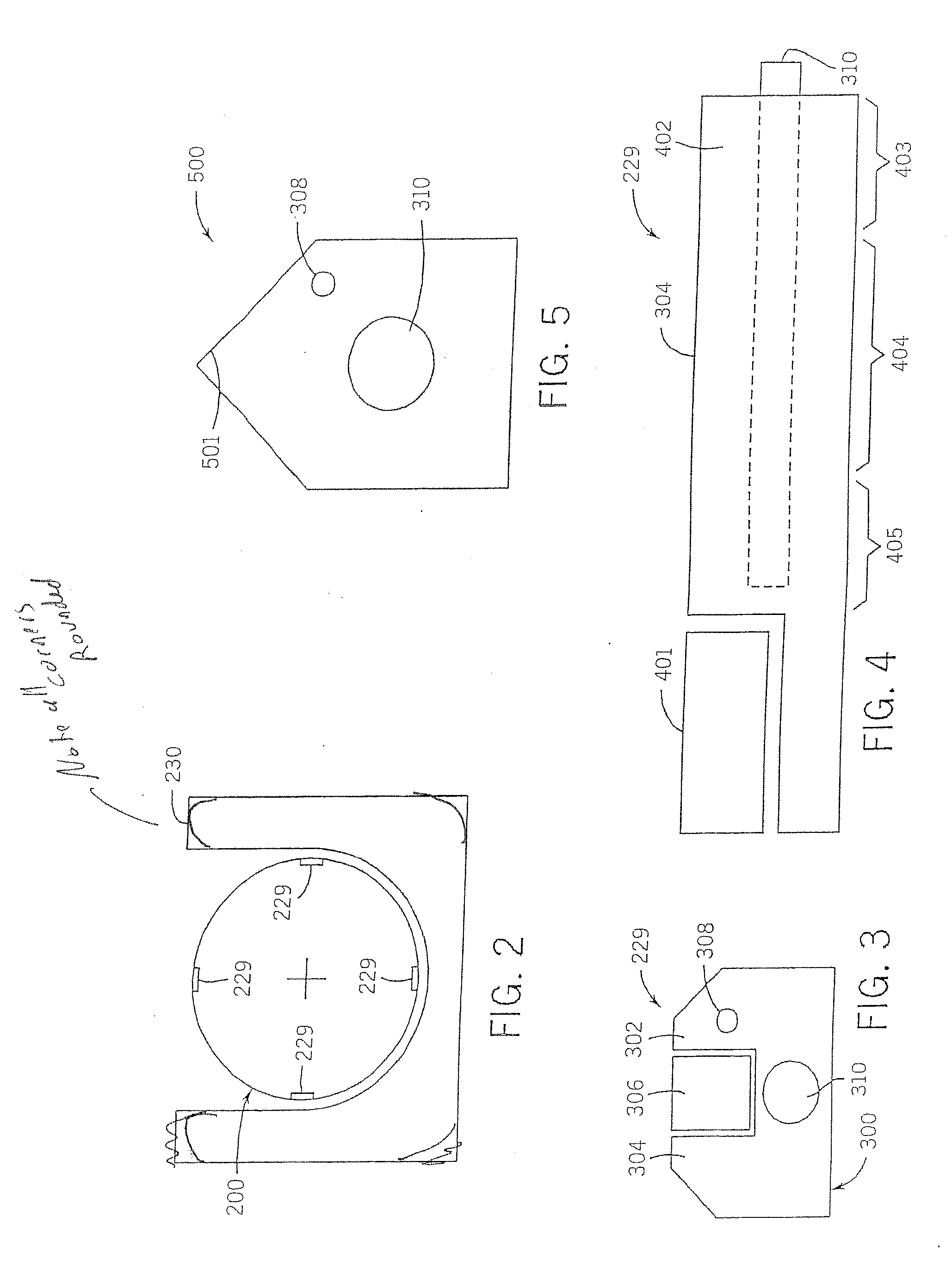
[0074] Generally, the present invention provides for a rotary bag machine with an input section, a drum section, and an output section. A perforation or line of weakness is formed on the rotary drum, for at least part of the time the seal is being form...


PUM

PropertyMeasurementUnit
speedaaaaaaaaaa
lengthaaaaaaaaaa
lengthaaaaaaaaaa

Abstract

A machine and method for making bags is described and includes a web traveling from an input section to a rotary drum, to an output section. The rotary drum includes at least one seal bar, having a single sealing zone, and an weakening zone disposed within the single sealing zone. The single sealing zone may be a heated perforator, includes a heating wire. The heating wire may be an NiCr wire and make intermittent contact with the web and be disposed in an insert. The weakening zone may create a line of weakness that is uniform or varies in intensity. The sealing zone may include temperature zones, cartridge heaters, cooling air, or heated air, or a source of ultrasonic, microwave or radiative energy.

Description

FIELD OF THE INVENTION [0001] The present invention relates generally to the art of bag making. More specifically, it relates to bag making machines and a bag making method that create bags from a film or web and form seals and perforations or a line of weakness separating adjoining bags made from the web. BACKGROUND OF THE INVENTION [0002] There are many known bag machines. One style is a rotary drum machine. Rotary drum machines are well known, and a detailed description may be found in U.S. Pat. Nos. 6,117,058, 4,934,993, 5,518,559, 5,587,032 and 4,642,084 (each of which is hereby incorporated by reference). [0003] A detailed description of the operation of rotary bag machines may be found in the patents above, but their general operation may be seen with respect to FIG. 1. A prior art rotary bag machine 100 continuously processes a web 201 using a dancer assembly 203, a pair of drum-in rolls 205 and 206 (203-206 are part of an input section), a sealing drum 208, a pair of drum-o...

Claims


Application Information

Patent Timeline
Patent Type & Authority Applications(United States)
IPC IPC(8): B32B37/30B31B50/10B31B50/16B31B50/28B31B50/64B31B70/00
CPCB29C65/10B29C65/14B29C65/1412B29C65/1425B29C65/1467B29C65/16B29C65/18B29C65/38B29C65/7412B29C65/7433B29C65/7437B29C65/7451B29C65/7453B29C65/7457B29C66/0042B29C66/232B29C66/3472B29C66/348B29C66/349B29C66/7352B29C66/80B29C66/8122B29C66/81262B29C66/81267B29C66/818B29C66/83511B29C66/8511B29C66/91231B29C66/919B29C66/939B29C66/949B29C2035/0822B29C2793/0045B29K2023/0625B29K2905/02B31B1/74B31B19/14B31B27/00B31B2201/61B31B2219/028B31B2219/14B31B2219/924B31B2237/60B31B1/10B29C65/1496B29C65/222B29C65/305B29C65/229B29C65/7847B29C66/83417B29C66/83433B29C66/83517B29C65/1696B29C66/91653B29C66/81417B29C66/81419B29C66/81427B29C66/1122B29C66/43B29C66/91423B29C66/93451B29C66/81812B29C66/91212B29C66/91315B29C66/962B29C66/961B29C66/91651B29C66/91421B29C66/91431B29C66/91631B29C66/91641B29C66/81431Y10T156/1054Y10T156/1313B29K2827/18B29C65/00B29C66/9141B29K2995/007B29C66/81264B29C66/81241B29C66/71B31B2160/10B31B70/14B31B2155/00B31B2160/20B31B50/741B31B70/024B31B70/946B31B2155/003Y10T83/9408Y10T83/0414Y10T83/293Y10T83/9292B31B70/00B31B70/146B29K2909/08B29L2031/7128
Inventor SELLE, PAUL A.RADTKE, KENNETH C.SAUDER, CHARLES H.JOHNSON, PAUL A.WHITE, CHRISTOPHER LEEJOHNSON, ARVID R.PRELLWITZ, GREGORY T.STICKNEY, MICHAEL J.JANSEN, THOMAS C.SAUCIER, CHRISTOPHER A.LEITZKE, TERRY L.SCHMOLL, BRADLEY J.SCHRLIES, CHRISJOHNSON, GREGORYGRASSE, SCOTT
Owner CMD CORP
Why Eureka
Try Eureka