Air driven spindle assembly

a technology of air drive and spindle head, which is applied in the direction of machines/engines, rotary piston liquid engines, process and machine control, etc., can solve the problem of beyond the capability of the cnc machine spindle head, and achieve the effect of easy speed adjustmen

Active Publication Date: 2008-04-24
BRYAN STEVE M
View PDF13 Cites 6 Cited by
  • Summary
  • Abstract
  • Description
  • Claims
  • Application Information

AI Technical Summary

Benefits of technology

[0015]An advantage of the present invention is that the speed is governed by an internal adjustable mechanism of the spindle assembly.
[0016]Another adva...

Problems solved by technology

Externally powered tools, such as an air driven turbine put out an extremely high-speed rotat...

Method used


Image

  • Air driven spindle assembly
  • Air driven spindle assembly
  • Air driven spindle assembly

Examples


Embodiment Construction

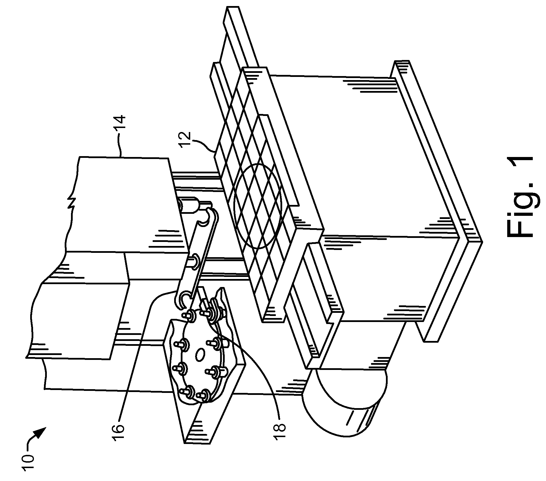
[0024]Referring now to the drawings, and more particularly to FIG. 1, there is shown a machining center 10 having a table 12, a head 14, a tool changer 16 and at least one air driven spindle assembly 18. Machining center 10 is also known as a computer numerically controlled (CNC) machine center 10 that has a power driven head 14 that rotates a tool for cutting material fastened to table 12. Tool changer 16 automatically changes tools that are used in head 14 of machine center 10. An air driven spindle assembly 18 may be utilized in head 14, which is normally not rotated in head 14 but rather is driven by an air supply provided by machine center 10 for the driving of a cutting tool that may be attached to air driven spindle assembly 18.

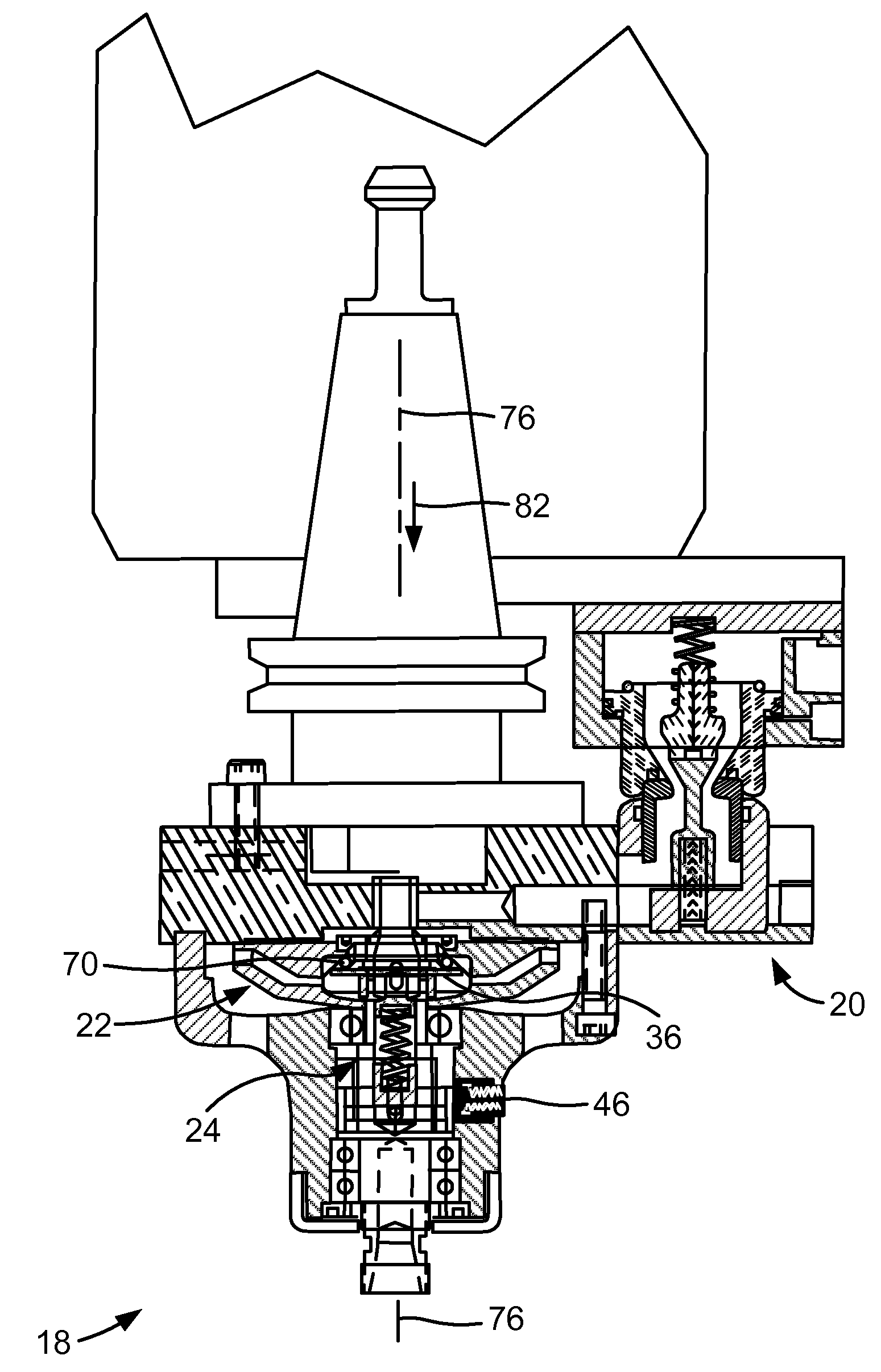
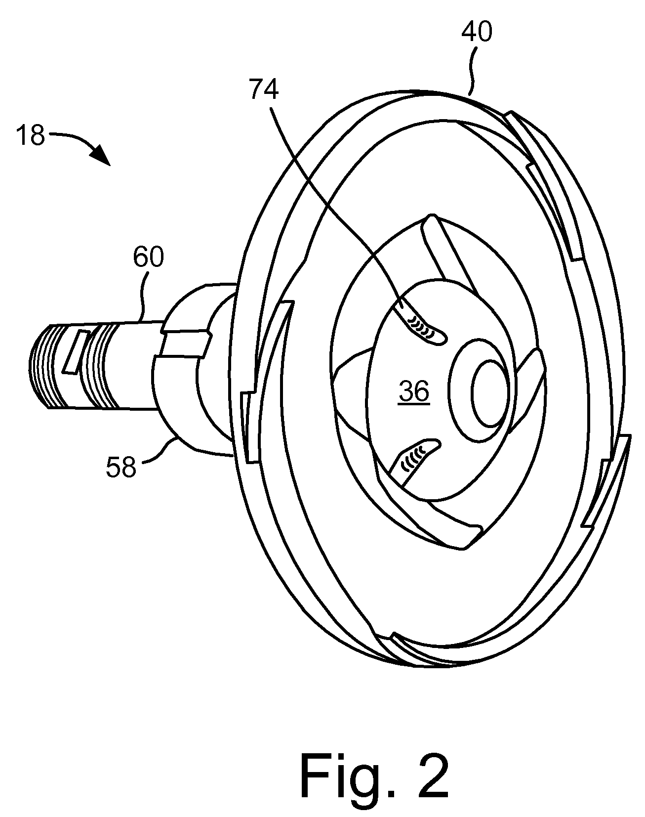
[0025]Now, additionally referring to FIGS. 2-5 there is illustrated air driven spindle assembly 18 that includes an air connection assembly 20, an air turbine assembly 22 and an adjustable speed regulator assembly 24. The air turbine assembly incorpora...


PUM

PropertyMeasurementUnit
Speedaaaaaaaaaa

Abstract

An air driven tool for use in a machining center, the air driven tool including an adjustable speed regulator and a turbine. The turbine is driven by pressurized air directed thereto. The turbine is rotatable about an axis. A flow of the air is regulated by the adjustable speed regulator. The adjustable speed regulator includes a biasing member, an inclined annular surface, a regulator plate and a plurality of moveable bearings. The inclined annular surface has an angle relative to the axis. The plurality of movable bearings are positioned between the inclined annular surface and the regulator plate. The biasing member biases the inclined annular surface and/or the regulator plate toward each other.

Description

CROSS REFERENCE TO RELATED APPLICATIONS[0001]This is a non-provisional application based upon U.S. provisional patent application Ser. No. 60 / 829,922, entitled “AIR DRIVEN SPINDLE ASSEMBLY”, filed Oct. 18, 2006, which is incorporated herein by reference.BACKGROUND OF THE INVENTION[0002]1. Field of the Invention[0003]The present invention relates to a machining center, and, more particularly, to an air driven spindle assembly insertable into a machining center.[0004]2. Description of the Related Art[0005]The abbreviation “CNC” stands for computer numerical control, and refers specifically to a computer “controller” that reads coded instructions and uses them to direct the driving of a machine tool. The machine tool may be a powered mechanical device used to fabricate components by the selective removal of material. A CNC machine may use interpolation of a cutting tool in the working envelope of the machine. The operating parameters of the CNC can be altered by way of software updates...

Claims


Application Information

Patent Timeline
IPC IPC(8): B23Q5/54
CPCB23Q5/06Y10S415/904Y10T409/309352Y10T409/309296Y10S408/702B23Q2220/008Y10T137/1135
Inventor BRYAN, STEVE M.
Owner BRYAN STEVE M
Why Eureka
Try Eureka