Method and apparatus for pwm control of voltage source inverter to minimize current sampling errors in electric drives

Inactive Publication Date: 2008-04-24
GM GLOBAL TECH OPERATIONS LLC
View PDF6 Cites 21 Cited by
  • Summary
  • Abstract
  • Description
  • Claims
  • Application Information

AI Technical Summary

Problems solved by technology

However, most PWM techniques add a ripple current onto the motor currents that can cause errors in the s

Method used


Image

  • Method and apparatus for pwm control of voltage source inverter to minimize current sampling errors in electric drives
  • Method and apparatus for pwm control of voltage source inverter to minimize current sampling errors in electric drives
  • Method and apparatus for pwm control of voltage source inverter to minimize current sampling errors in electric drives

Examples


Embodiment Construction

[0022]The following detailed description is merely exemplary in nature and is not intended to limit the invention or the application and uses of the invention. Furthermore, there is no intention to be bound by any expressed or implied theory presented in the preceding technical field, background, brief summary or the following detailed description.

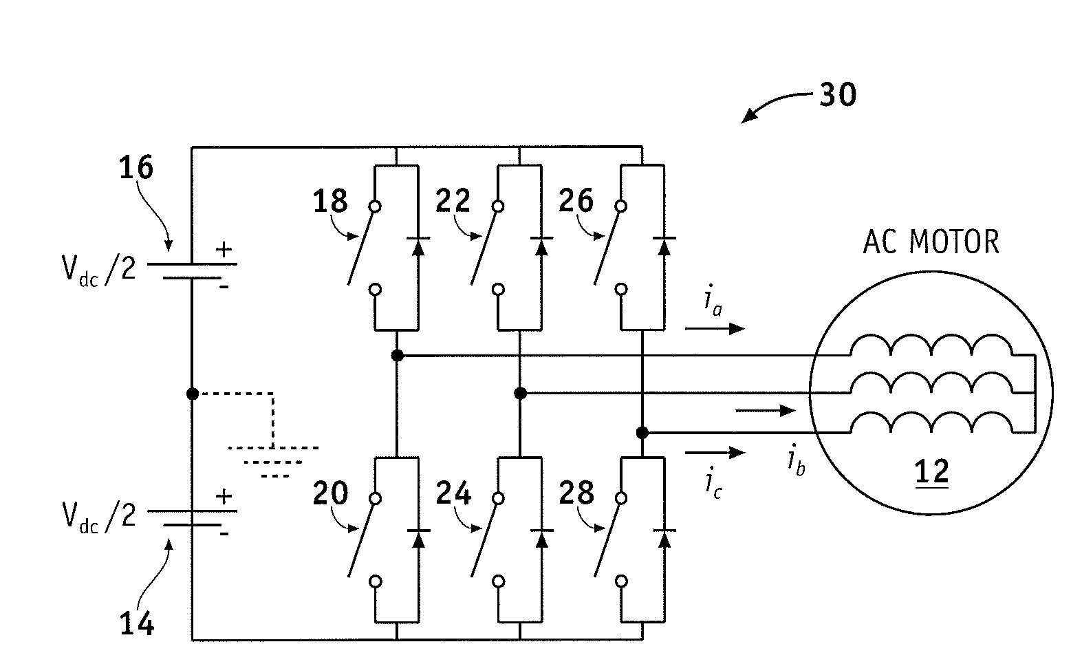
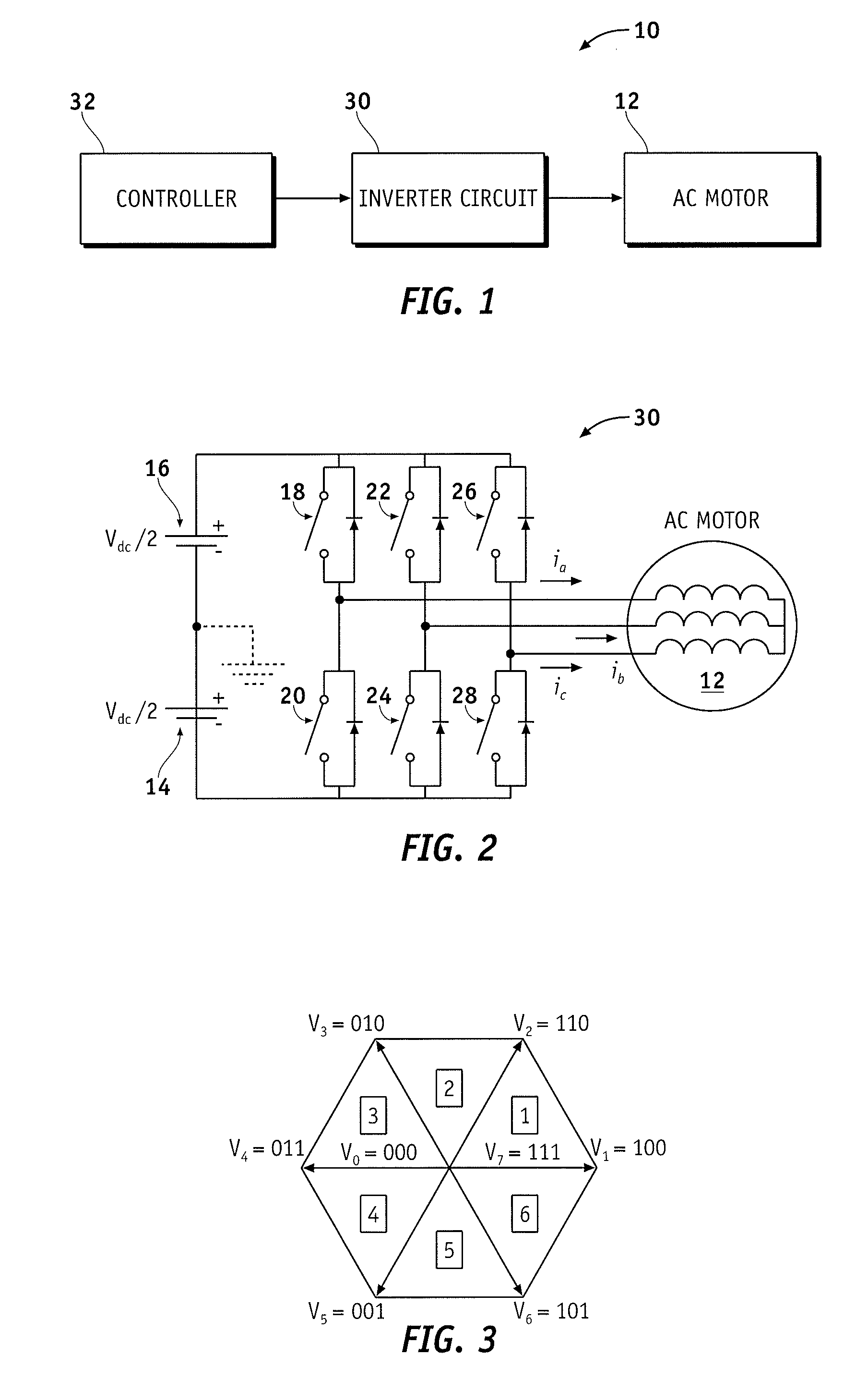
[0023]Referring to FIG. 1, a voltage source inverter system 10 is shown in accordance with an exemplary embodiment of the present invention. The voltage source inverter system 10 comprises a controller 32, an inverter circuit 30 coupled to an output of the controller 32, and an alternating current (AC) motor 12 coupled to a first output of the inverter circuit 30. Generally, the controller 32 produces a Pulse Width Modulation (PWM) signal for controlling the switching action of the inverter circuit 30, although the controller can also receive the PWM signal from another source, for example, a modulator. In an exemplary embodiment, the cont...


PUM


Abstract

A method for controlling an alternating current (AC) motor includes choosing a pulse sequence based on a ripple current in the AC motor at a sampling instant; and providing a voltage to the AC motor based on the pulse sequence.

Description

TECHNICAL FIELD[0001]The present invention generally relates to a voltage source inverter system, and more particularly relates to an apparatus and method for controlling the output voltage component of a voltage source inverter system such that current sampling errors are minimized.BACKGROUND OF THE INVENTION[0002]AC motors are used in a variety of applications, including vehicle applications such as traction control. The AC motors used in vehicle applications are typically controlled via a voltage source inverter system. Discontinuous Pulse Width Modulation (DPWM) methods are commonly employed in the controllers of voltage source inverter systems to control the fundamental output voltage component of three phase voltage source inverters of the system. These three-phase voltage source inverters may in turn be used to control the phase currents of three phase AC motors. DPWM methods reduce inverter losses in comparison with continuous Pulse Width Modulation (PWM) methods, such as si...

Claims


Application Information

Patent Timeline
IPC IPC(8): H02P27/08H02P27/00
CPCH02P27/08
Inventor WEST, STEPHEN T.WELCHKO, BRIANSCHULZ, STEVEN E.HITI, SILVA
Owner GM GLOBAL TECH OPERATIONS LLC
Why Eureka
Try Eureka