Article case with RFID tag and RFID system

a technology of rfid tags and cases, applied in the field of articles cases with rfid tags and rfid systems, can solve the problems of inconvenient transportation, metal cannot be used as the material of the case, and information from the rfid tags cannot be correctly read, etc., and achieve the effect of high portability

Inactive Publication Date: 2008-04-24
IBM CORP
View PDF10 Cites 50 Cited by
  • Summary
  • Abstract
  • Description
  • Claims
  • Application Information

AI Technical Summary

Benefits of technology

[0023] A method for managing an article according to an aspect of the present invention comprises: obtaining a case, the case including a built-in antenna for communicating with an RFID tag attached to an article enclosed within the case, with an external coaxial connector or an intermediary patch antenna connected to the built-in antenna and disposed on an outer surface of the case; disposing the article in the case such that a face of the article to which the RFID tag is attached is opposed to an antenna face of the built-in antenna; obtaining an RFID reader / writer for accessing the RFID tag; connecting the RFID reader / writer to the external coaxial connector of the case with a coaxial cable or bringing an antenna of the RFID reader / writer close to the intermediary patch antenna, with the antenna of the RFID reader / writer opposed to the intermediary patch antenna, thereby enabling communication; and causing the built-in antenna to generate radio waves via the coaxial cable or the intermediary patch antenna to resonate an antenna of the RFID tag with the radio waves such that the RFID reader / writer accesses the RFID tag attached to the article. The method further includes connecting an intermediary antenna separate from the case to the external coaxial connector, thereby enabling communication.
[0024] A case according to the invention is lightweight and has high portability because it contains only a transmitting-receiving antenna and RFID tags and has no RFID reader / writer and no power supply. Moreover, the “case” includes not only portable cases but also any shape and size of boxes and bags including large-size boxes for use in the distribution industry, such as large-size housings or containers. This invention is particularly suitable for hard metal cases for magnetic tape or other valuables with RFID tags. It is suitable not only for metal cases but also for cases with low electromagnetic-wave transmittance because of the material or thickness of thereof. The invention is characterized in that a metal case with low electromagnetic-wave transmittance directly receives electric power from the exterior via a cable or radio wave, and applies radio-frequency energy to the built-in transmitting-receiving antenna in the case by coupling electric and magnetic fields for communication with the RFID tags.

Problems solved by technology

Thus, such RFID tags, when metal is present in the front, back, or periphery, have the problem that information from the RFID tags cannot be correctly read because magnetic fields and radio waves are reflected or absorbed by the metal.
In this case, to carry out a communication between an RFID reader / writer and an RFID tag from the exterior of the case, metal cannot be used as the material of the case because it is an obstacle to communication.
This is not suitable for transportation because of the heavy metal case including the reader, the power supply unit and other components.
However, this arrangement needs to provide antennas on all the sides of the returnable box and requires such a complicated operation as to switch the antennas and as such, the returnable box would become complicated in structure, and have an increased weight.
In this case, to read identification information (ID) of RFID tags, it is necessary to open every case and bring an RFID reader / writer to articles, resulting in low work efficiency.
Moreover, for security or safe management, it would be an important challenge to read the information of ID tags attached to valuables without opening the metal transportation case.

Method used


Image

  • Article case with RFID tag and RFID system
  • Article case with RFID tag and RFID system
  • Article case with RFID tag and RFID system

Examples


Embodiment Construction

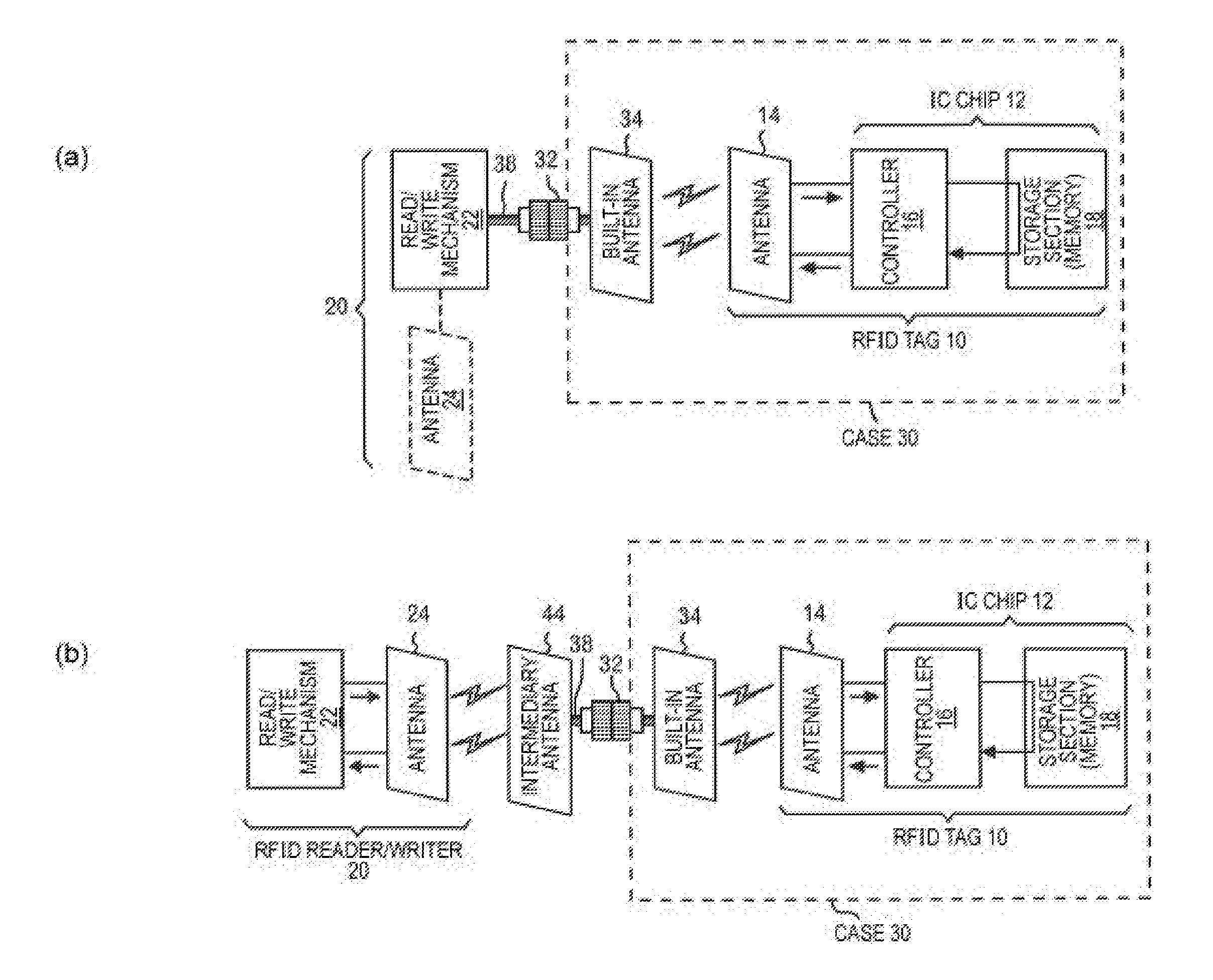
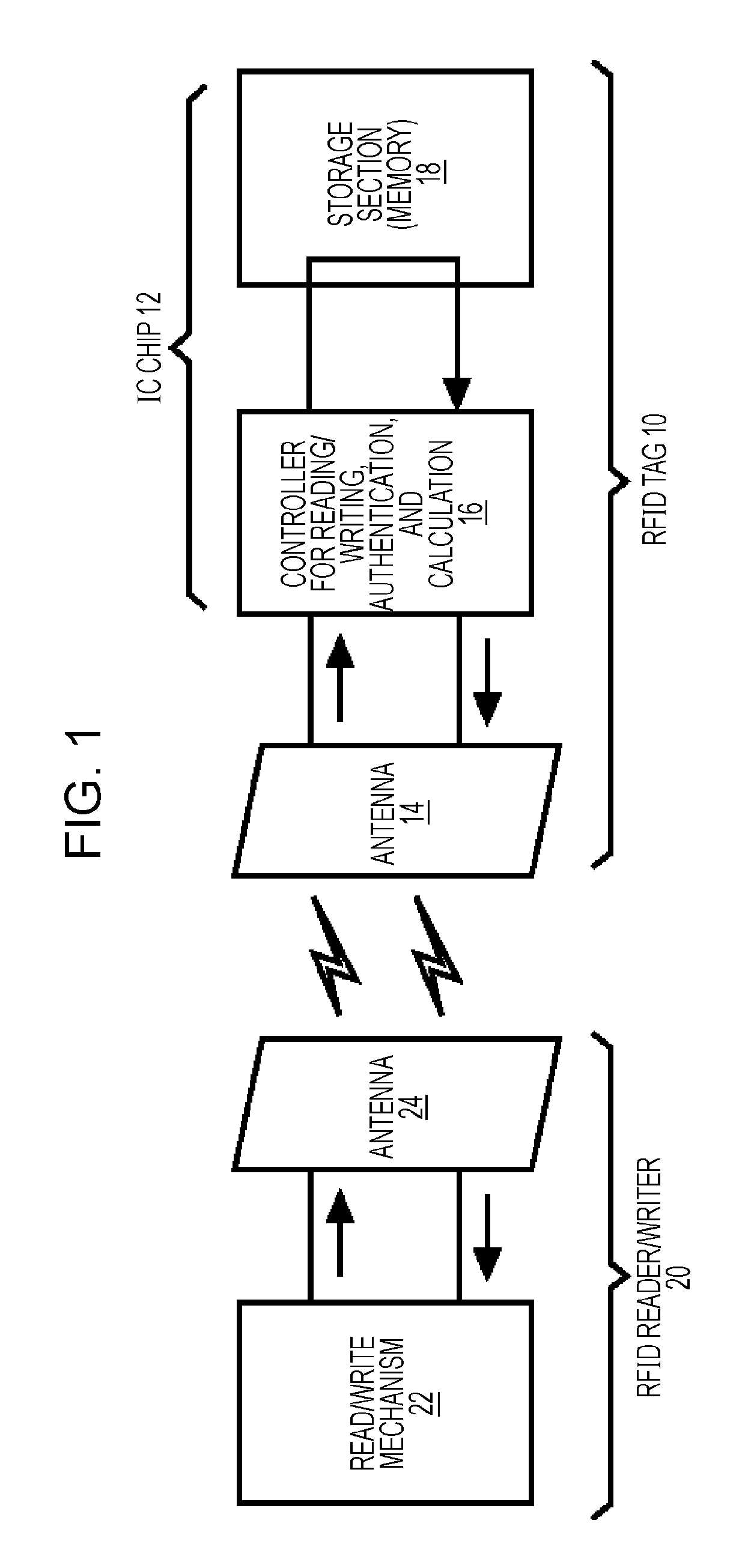
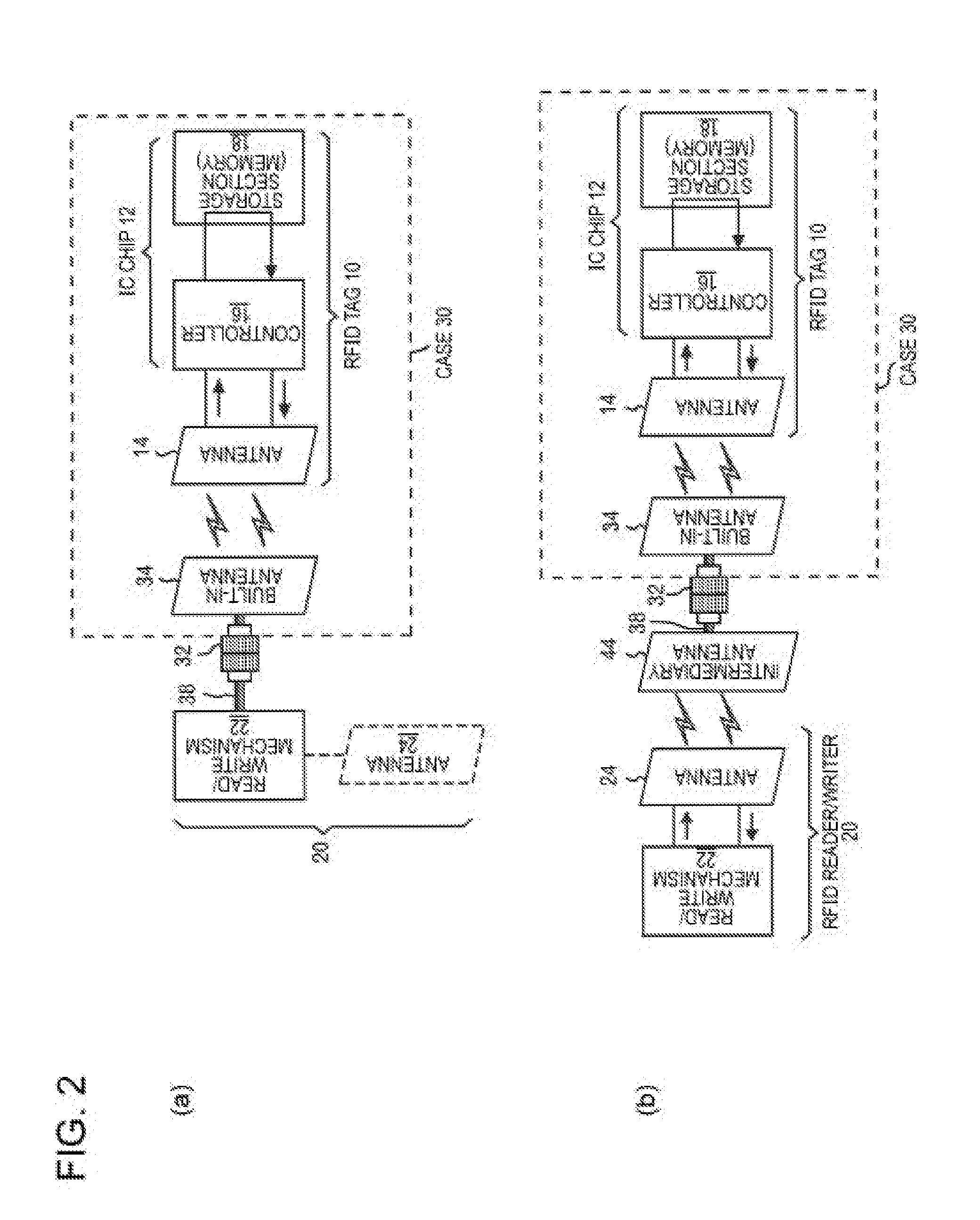
[0036]FIG. 1 is a schematic block diagram of a system including an RFID reader / writer 20 that accesses an RFID tag 10 and the information of the RFID tag 10 used in the invention. This system is generally referred to as an electromagnetic coupling type, in which signals are transferred by the resonance of antennas. Radio frequencies used in this system are around 2.45 GHz and 950 MHz (UHF band), which normally provide communication ranges of about one meter and three meters, respectively, thus providing wide applications. The system of the electromagnetic coupling type will be described hereinbelow by way of example. RFID tags designed to the respective frequencies are selected. The RFID reader / writer 20 is generally also referred to as a reader or a scanner, which can be applied both to reading and writing of the information in the IC chips of RFID tags. The reading and writing are hereinafter referred to as “access”.

[0037] The RFID tag 10 has the function of changing radio energy...


PUM


Abstract

The present invention is directed to an article case for accessing information on an RFID tag attached to an article enclosed in the case, and an RFID system using the case. An article case in accordance with an embodiment includes: a built-in antenna communicating with the RFID tag attached to the article; and a communication structure connected to the built-in antenna and disposed on an outer surface of the case, for communicating with an external RFID reader/writer.

Description

BACKGROUND OF THE INVENTION [0001] 1. Field of the Invention [0002] The present invention relates to a case for enclosing articles with an RFID tag and an RFID system using the case, and more specifically, the present relates to a high-safety case and an RFID system in which information of the articles in the case can be read from or written to the RFID tags attached to the articles. [0003] 2. Related Art [0004] Methods for reading and writing from / to a radio frequency identification tag (an RFID tag) include inductive coupling and electromagnetic coupling, which use electromagnetic induction by a magnetic field and radio waves of antennas, respectively. Both methods employ non-contact communication with an RFID reader / writer (or an IC tag scanner). [0005] An RFID tag includes an antenna and an IC chip. When the antenna receives electric power and a signal from the RFID reader / writer, the controller of the IC chip accumulates the received electric power in a capacitor, and sends inf...

Claims


Application Information

Patent Timeline
Patent Type & Authority Applications(United States)
IPC IPC(8): G08B13/14B65D25/20G06K7/00G06K7/10G06K17/00G06K19/07
CPCA45C5/04A45C15/00B65D2203/10G06K19/0723G06K7/0008G06K7/10178E05G1/005E05G1/00G06K19/07
Inventor KAORU, FUKUDA
Owner IBM CORP
Why Eureka
Try Eureka