
Optical Turnaround

a technology of optical turnaround and optical fiber, applied in the field of optical fiber sensor systems, can solve the problems of tightness, inconvenient operation of wellbore operations, and limited wellbore operations by natur

Inactive Publication Date: 2008-04-24
SCHLUMBERGER TECH CORP
View PDF19 Cites 21 Cited by
  • Summary
  • Abstract
  • Description
  • Claims
  • Application Information

AI Technical Summary

Problems solved by technology

Wellbores by their nature are very limited in space and wellbore operations require conservative utilization of this space.
This space limitation is one of the attractive features of fiber optic sensors.
However, there are some shortcomings and drawbacks in the current fiber optic sensor technology, in particular in regard to reservoir monitoring using distributed temperature sensors (“DTS”).
Simply bending the fiber tightly is not a satisfactory option because tight bends can cause high bending losses and high bending stresses which increase the probability of fiber failures over time.
Several drawbacks are associated with these methods, including the requirement of specialized equipment and algorithms to precisely control the tapered transition region between the original fiber diameter and the reduced diameter section; and that the reduced diameter section is extremely fragile.
These drawbacks are very significant and limiting in the context of fiber optic installations in wellbores.
Wellbores provide very harsh and challenging conditions.
Often wellbores encounter very high temperatures, pressures and equipment vibrations from fluid flow.
The wellbore environment is very turbulent or violent.
Also, the fibers are typically run as part of a fiber optic cable, thus the size of the cable and the space occupied in the wellbore can be significant.

Method used


Image

  • Optical Turnaround
  • Optical Turnaround
  • Optical Turnaround

Examples


Embodiment Construction

[0018]Refer now to the drawings wherein depicted elements are not necessarily shown to scale and wherein like or similar elements are designated by the same reference numeral through the several views.

[0019]As used herein, the terms “up” and “down”; “upper” and “lower”; and other like terms indicating relative positions to a given point or element are utilized to more clearly describe some elements of the embodiments of the invention. Commonly, these terms relate to a reference point as the surface from which drilling operations are initiated as being the top point and the total depth of the well being the lowest point.

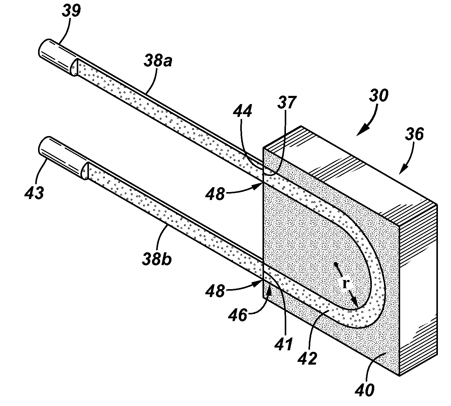
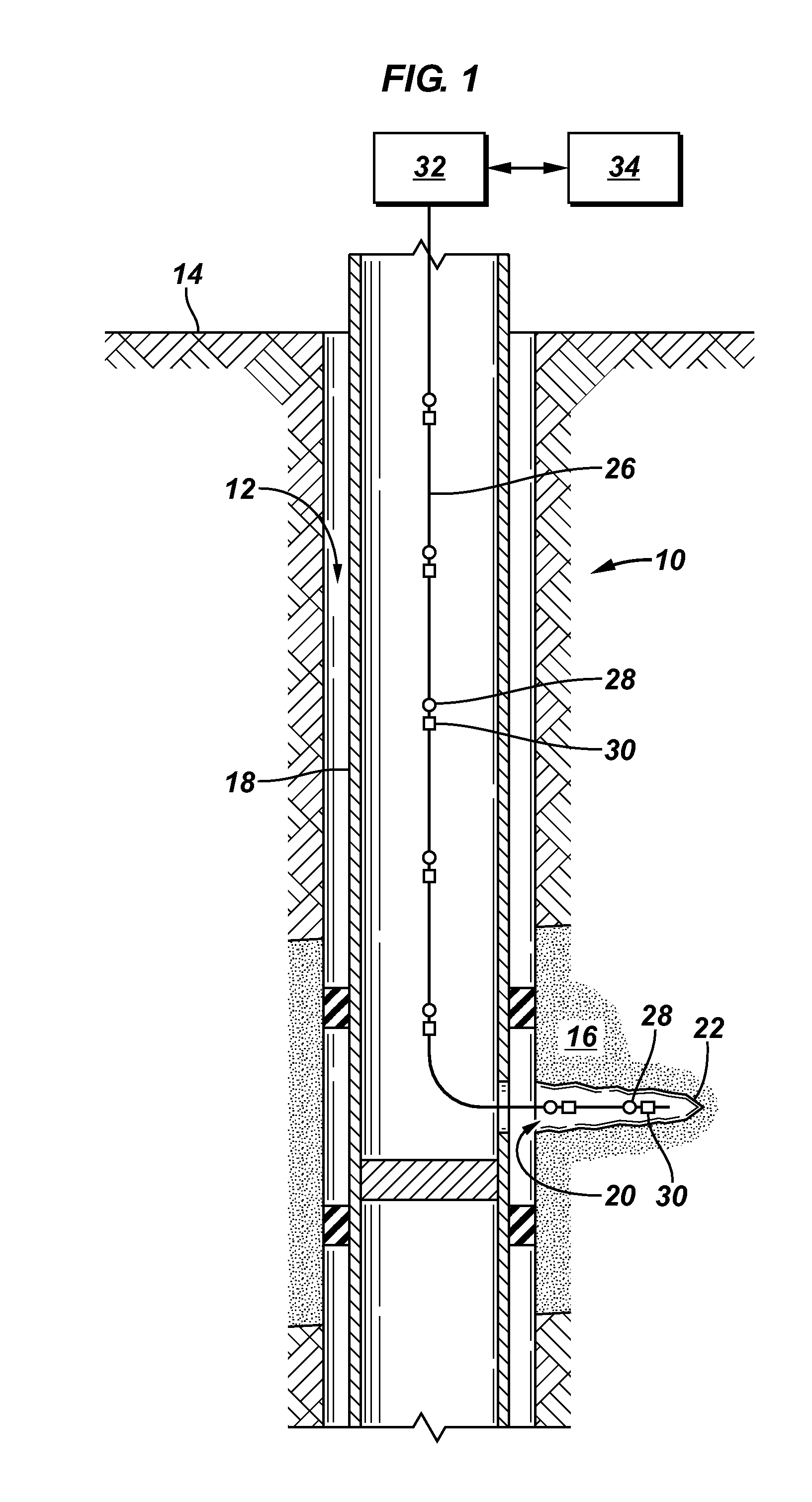
[0020]FIG. 1 is a schematic of an embodiment of a fiber optic sensor system of the present invention, generally denoted by the numeral 10. A wellbore 12 is drilled from the surface 14 of the earth into an earthen formation 16. Wellbore 12 may include casing 18. Casing 18 may be perforated 20 to form channels 22 into a desired portion of formation 16. Wellbore 18 may b...


PUM


Abstract

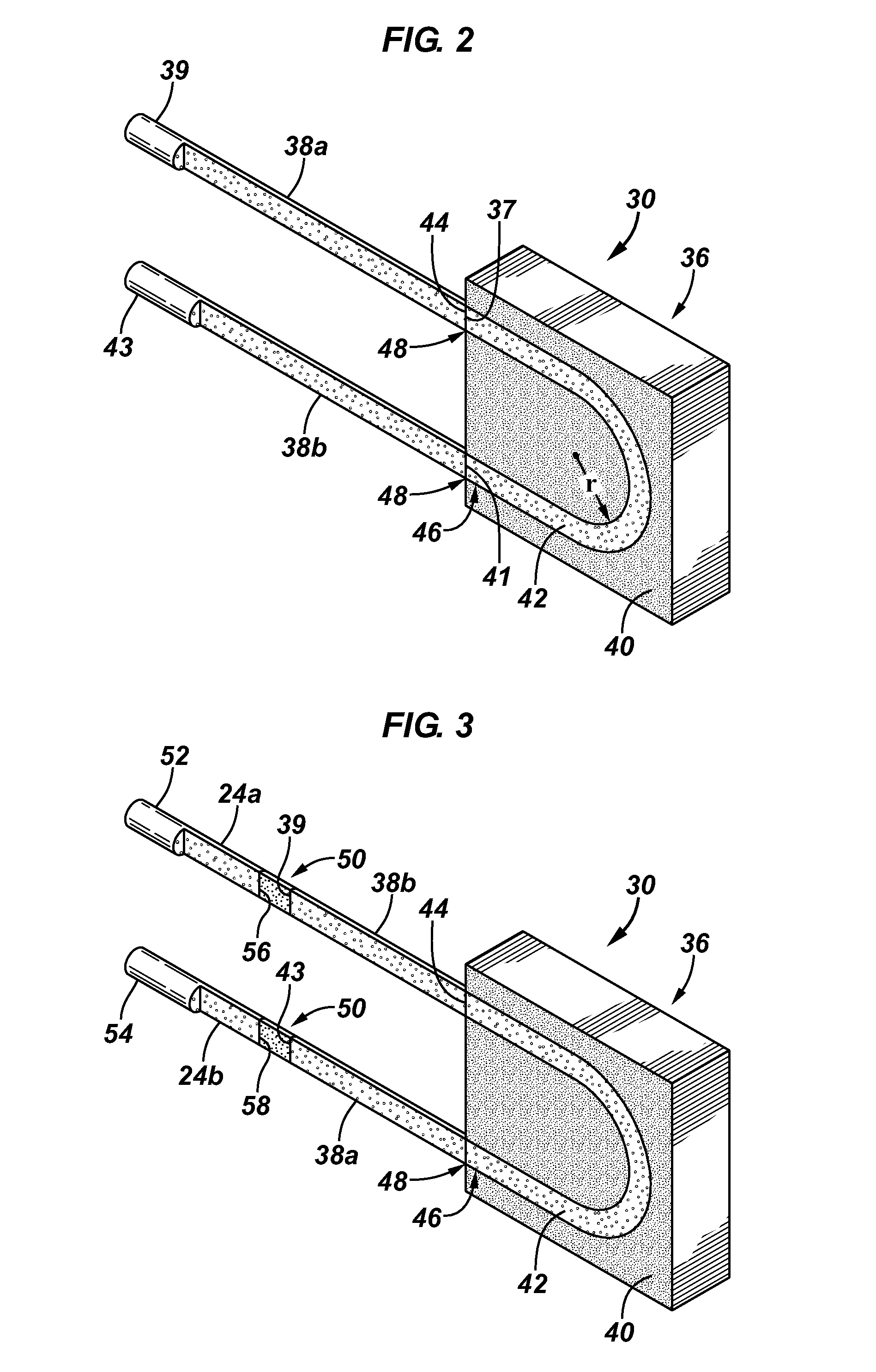
Fiber optic sensors commonly require a 180 degree turnaround to form a continuous optical circuit. Methods and apparatus for providing 180 degree turnarounds in a fiber optic system that include a shorter radius turnaround then provided by micro-bending the optic fiber are desired. An embodiment of a turnaround apparatus includes a first optic fiber pigtail, a second optic fiber pigtail, and an optical waveguide forming a U-shaped path having an input end optically connected to a first end of the first pigtail and an output end optically connected to a first end of the second pigtail.

Description

FIELD OF THE INVENTION[0001]The present invention relates in general to optical fiber sensor systems utilized in wellbore applications and more specifically to methods and apparatus for affecting a turnaround in a fiber optic cable in a small space without micro-bending the fiber.BACKGROUND[0002]In wellbore operations it is beneficial to know the downhole conditions in the wellbore and the surrounding formations. Some examples of downhole conditions or parameters, without limitation, are pressure, temperature, flow and chemical activity. Monitoring of these parameters is beneficial throughout the life of the wellbore and surrounding formation. For example, it is beneficial to monitor these parameters during drilling operations, during production or injection intervals, formation treatment operations (i.e., acidizing, fracturing) and when the wells are shutin. It is further desired, at times to monitor formation parameters away from the producing and injection wellbores by drilling m...

Claims


Application Information

Patent Timeline
IPC IPC(8): G02B6/26G02B6/42G02B6/00
CPCE21B47/00G02B6/30G02B6/125E21B47/123E21B47/135G02B6/262G02B6/264E21B47/06
Inventor VARADARAJAN, HARINIMEYYAPPAN, RAMASWAMY
Owner SCHLUMBERGER TECH CORP
Learn More