Variable speed accessory drive system

Inactive Publication Date: 2008-04-24
GM GLOBAL TECH OPERATIONS LLC
View PDF9 Cites 46 Cited by
  • Summary
  • Abstract
  • Description
  • Claims
  • Application Information

AI Technical Summary

Problems solved by technology

Therefore, at higher engine speeds, excess ene

Method used


Image

  • Variable speed accessory drive system
  • Variable speed accessory drive system
  • Variable speed accessory drive system

Examples


Example

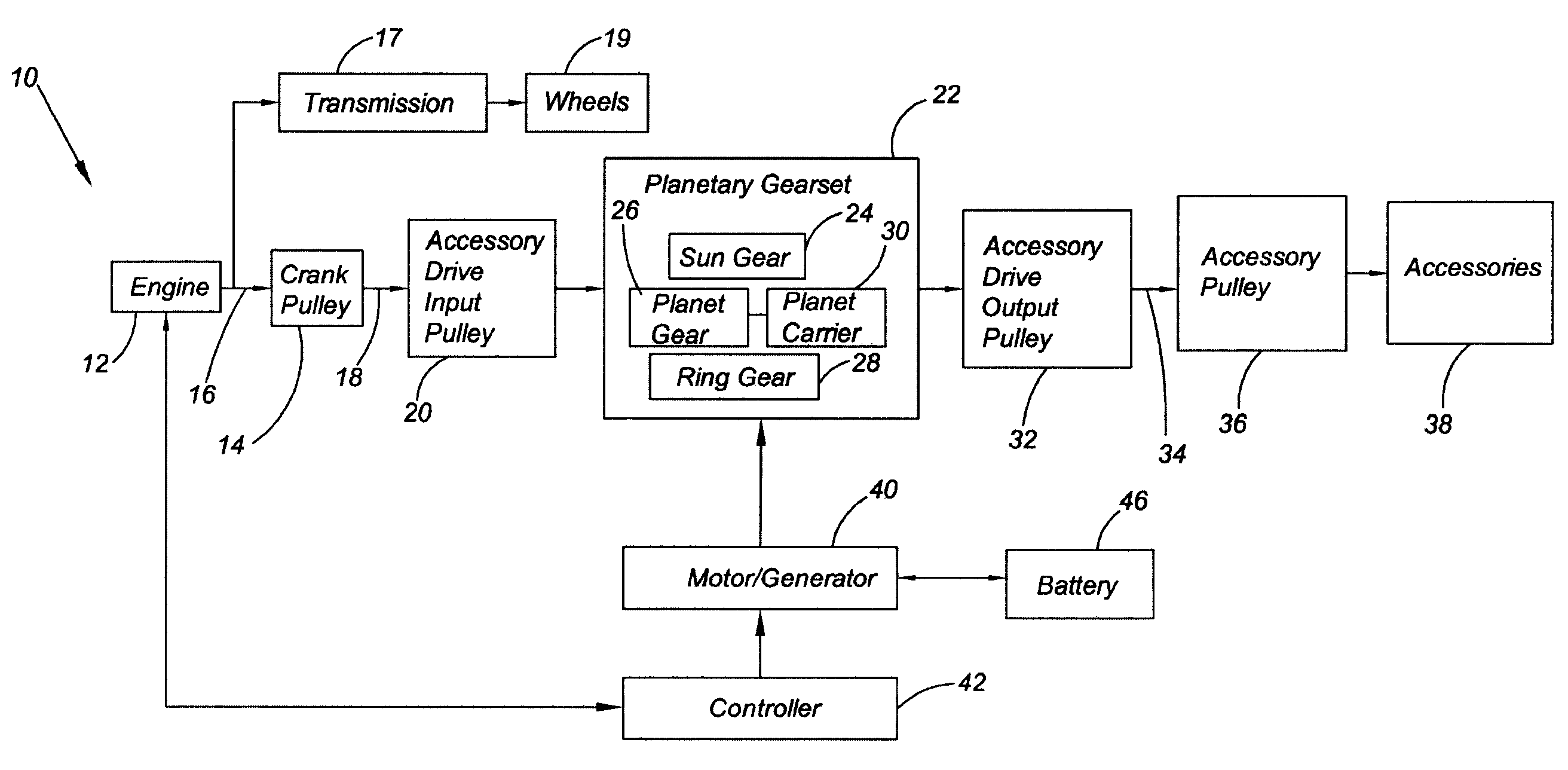
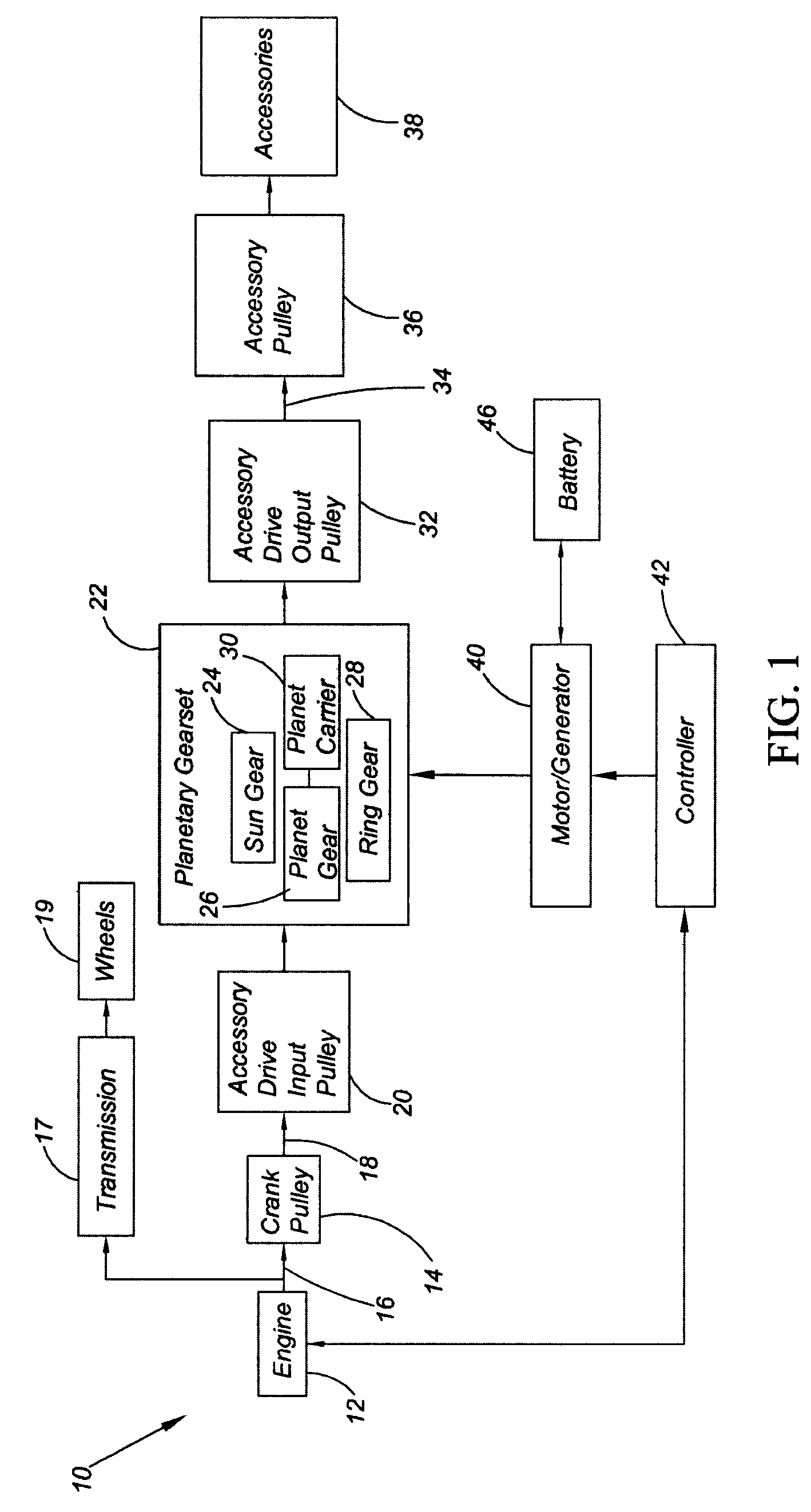
[0022]Conventional accessory drive systems operate by transferring engine output directly to the accessories so the accessories are driven at a speed directly proportional to engine speed. Since the engine operates over a wide speed range (e.g., between 500 rpm and 7,000 rpm), the accessories are typically designed to provide full capacity at the low end of the engine speed range in order to ensure they remain fully operational. Therefore, when the engine is operating at higher speeds, conventional accessory drive systems transfer more energy to the accessories than necessary to provide adequate function. The excess energy transferred to the accessories causes inefficiency and diminishes fuel economy. The accessory drive system 10 (shown in FIG. 1) of the present invention allows the accessories to be driven at a predetermined optimal speed independent from the speed at which the engine is running in order to improve fuel economy. The predetermined optimal speed at which the accesso...


PUM


Abstract

The present invention provides an accessory drive system for a vehicle. The accessory drive system includes a planetary gear set having a first, second, and third planetary member. A torque transfer device operatively connects an engine with the first planetary member. A motor/generator is operatively connected to the second planetary member, and a plurality of accessories are operatively connected to the third planetary member. Engine output is transferable through the planetary gear set to drive the accessories, and the speed at which the accessories are driven is selectable by controlling the speed of the motor/generator.

Description

TECHNICAL FIELD[0001]The present invention pertains generally to a variable speed accessory drive system for a vehicle.BACKGROUND OF THE INVENTION[0002]Driven accessories in a vehicle may include, for example, an air conditioning compressor, a power steering pump, and an alternator. These accessories are generally powered by output from the engine. Conventional automotive accessory drive systems include a drive pulley connected to an engine output shaft. A flexible chain or belt couples the drive pulley with a plurality of driven pulleys that are each operatively connected to an accessory. The operating speeds of the accessories in such a conventional drive system are directly proportional to the speed of the engine. Since the engine operates over a wide speed range (i.e., for example, between 500 rpm and 7,000 rpm), the accessories are typically designed to provide full capacity at the low end of the engine speed range in order to ensure that they remain operational. Therefore, at ...

Claims


Application Information

Patent Timeline
IPC IPC(8): F16H3/72
CPCB60K6/365B60K6/48B60K25/02Y02T10/6221B60W10/30B60W20/00F16H3/724B60W10/08Y02T10/62B60W10/115
Inventor SMITH, ANTHONY L.GECIM, BURAK A.USORO, PATRICK B.
Owner GM GLOBAL TECH OPERATIONS LLC
Why Eureka
Try Eureka