Stilts

a technology for stilts and lower legs, applied in the field of stilts, can solve the problems of metal construction of 515, high production cost, and difficulty in straightening, and achieve the effect of improving the quality and improving the stability of the lower leg braces

Inactive Publication Date: 2008-04-24
LIN JOE
View PDF26 Cites 10 Cited by
  • Summary
  • Abstract
  • Description
  • Claims
  • Application Information

AI Technical Summary

Benefits of technology

[0023] In a further embodiment of the invention, there is provided a buckle for the fastener assembly. The buckle comprises an elongated base plate having a pair of spaced apart parallel ears extending normally therefrom and a tang extending generally normally therefrom at a location spaced apart from the ears. The tang is positioned in a plane generally normal to the planes of the ears. The tang has a “C” shaped bend near an upper end thereof facing generally toward the ears. The lever arm has a first end and a second end. The first end of the lever arm is pivotally connected to the ears of the base plate. The lever arm has a length which is greater than a distance between the ears and the tang on the base plate and has an inside cross piece positioned to ride over an outer surface of the “C” shaped bend of the tang and snap the lever arm into a locked position in which the elongated base plate and the lever arm are generally parallel. A portion of the “C” shaped bend of the tang protrudes above an upper surface of the lever arm to permit the tang to be manually moved and the lever arm to be unlocked. The drag link has a first end and a second end. The first end of the drag link is pivotally connected to the lever arm at a location between the first end of the lever arm and the cross piece. The second end of the drag link is fitted with a hook or loop for engaging the item to be pulled toward the buckle. The tang provides a redundant locking mechanism to prevent the stilt attachment to the user to be accidently undone.

Problems solved by technology

The calf brace in described in U.S. Pat. No. 5,645,515 is constructed of metal and is expensive to produce.
Also, metallic calf braces are subject to fatigue cracks over time, and are not easy to straighten if bent by accident or abuse.
Also, the calf brace in U.S. Pat. No. 5,645,515 presents an inherent safety hazard during falls because of its metallic construction.

Method used


Image

  • Stilts
  • Stilts
  • Stilts

Examples


Embodiment Construction

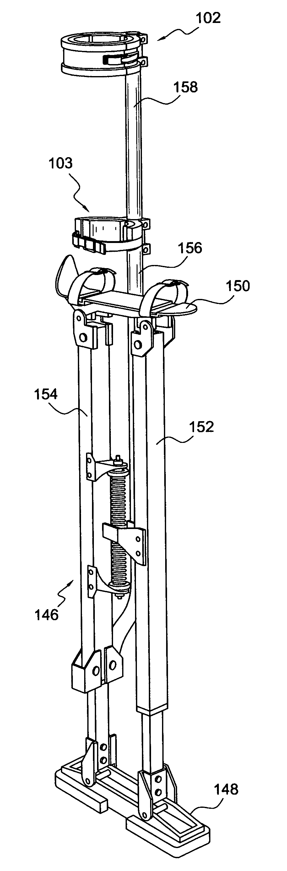
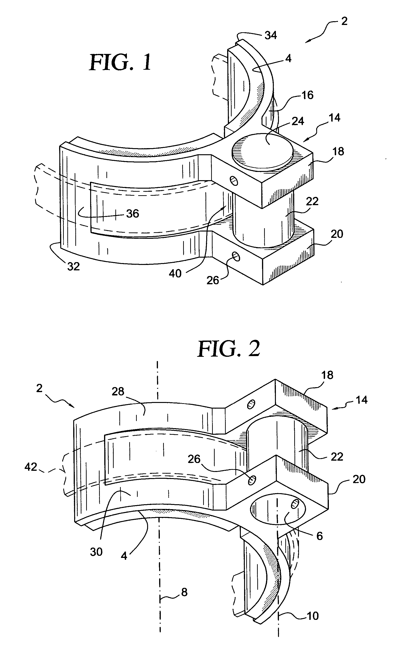
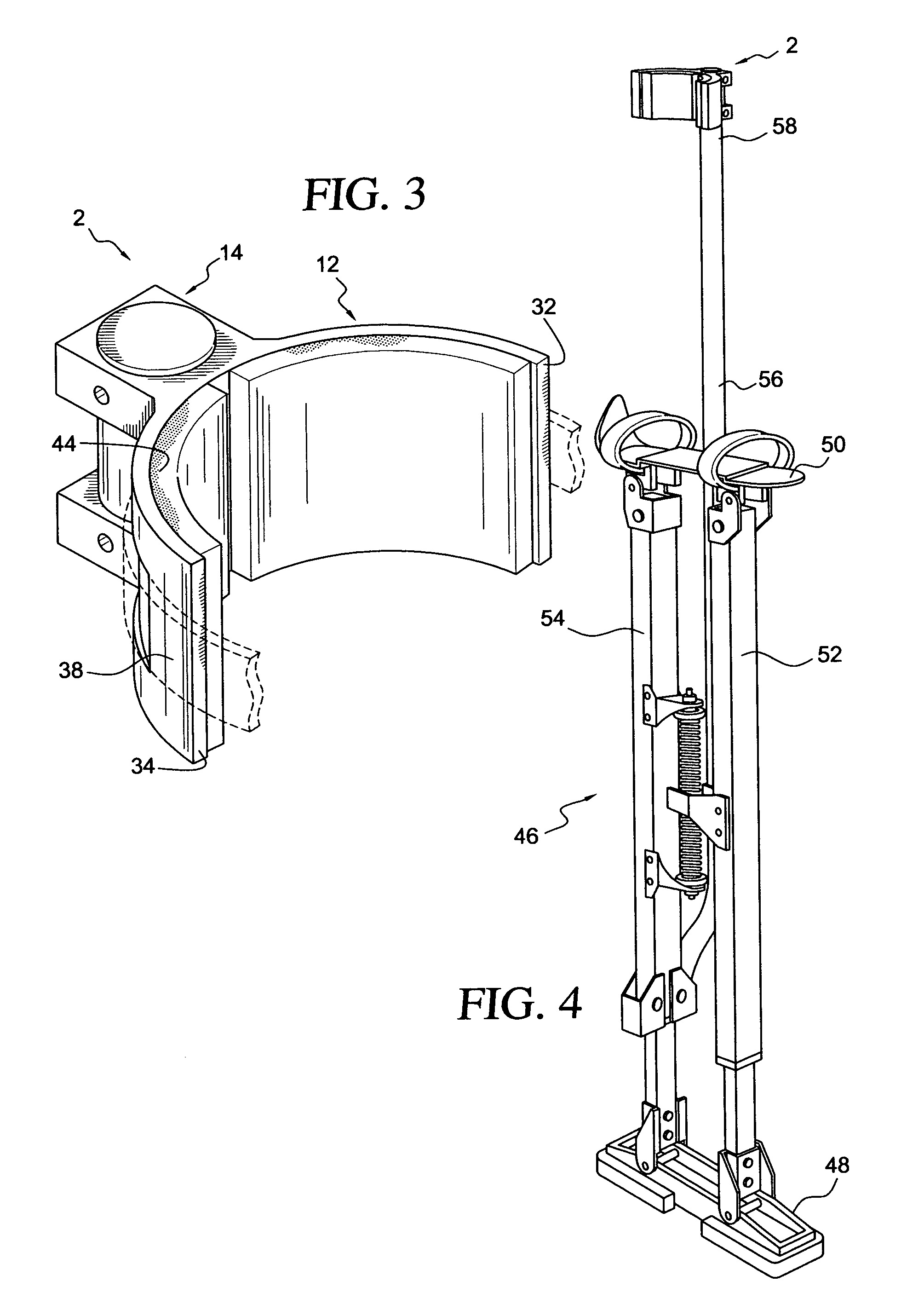
[0040] With reference to FIGS. 1 and 2, there is shown a non-flaccid lower leg brace element 2 for a stilt. The leg brace element comprises a nonflaccid body. The nonflaccid body defines a generally semi-cylindrical concave inside surface 4 for supporting a lateral side of a stilt user's leg, and a passage 6 spaced apart from the generally semi-cylindrical concave inside surface for receiving a leg support of the stilt.

[0041] A wide range of nonflaccid material is suitable for construction of the brace element 2. For cost and speed of production, a thermoplastic would be preferred. For strength, a fiber reinforced thermoplastic would be preferred. For durability, an engineering thermoplastic would be preferred. Short glass fiber reinforced polyetheretherketone (PEEK) is a suitable material, for example, as well as other nonflaccid items shown herein. The brace element 2, as well as the other nonflaccid items shown herein, is preferably produced by an injection molding process. More...


PUM


Abstract

A nonflaccid brace for construction stilts is disclosed. In one embodiment, the brace is employed as a lower leg brace. In another embodiment, the brace is employed as an ankle brace. In another embodiment, the brace is employed with one or more nonflaccid closures. An ankle brace for construction stilts is disclosed. In one embodiment, the ankle brace is positioned across the foot pad from the upright carrying the leg brace. A quick connect coupling for stilts is disclosed. The coupling can be employed to close the leg brace, the ankle brace, and/or the foot straps of the stilts.

Description

CROSS REFERENCE TO RELATED APPLICATIONS [0001] This application is a continuation in part of application Ser. No. 11 / 396,896 filed Apr. 3, 2006, now Ser. No. ______, and claims the benefit thereof.FIELD OF THE INVENTION [0002] In one aspect, this invention relates to improved lower leg braces for stilts, particularly stilts employed in the construction industry to facilitate overhead work, such as accessing and hanging suspended ceiling structures or overhead electrical or duct work. In another aspect, this invention relates to providing such stilts with an ankle brace. In a further aspect, this invention relates to improved foot retainers for such stilts. In an additional aspect, this invention relates to an improved fastener assembly for fastening such stilts to the user's body. BACKGROUND OF THE INVENTION [0003] U.S. Pat. No. 5,645,515, the disclosure of which is incorporated by reference herein, is an example of one type of stilt employed by the construction industry. It utilize...

Claims


Application Information

Patent Timeline
Patent Type & Authority Applications(United States)
IPC IPC(8): A63B25/00A44B11/00
CPCY10T24/4072A63B25/00
Inventor LIN, JOEMASAS, FERNANDO R.
Owner LIN JOE
Why Eureka
Try Eureka