Syringe Needle Sheath

a needle sheath and syringe technology, applied in the field of syringes, can solve the problems of high cost to society for supporting and providing medical attention to sufferers, needlestick injury to users, and relatively high cost of retractable syringes, so as to prevent or minimize the risk of needlestick injury and/or syringe re-us

Active Publication Date: 2008-04-24
UN HOLDINGS LLC
View PDF10 Cites 48 Cited by
  • Summary
  • Abstract
  • Description
  • Claims
  • Application Information

AI Technical Summary

Benefits of technology

[0011]The present invention is therefore broadly directed to syringe needle sheath operable to prevent or minimize the risk of needlestick injury and / or syringe re-use and which overcomes one or more disadvantages of the prior art or at least provides a commercially suitable alternative.

Problems solved by technology

The practice of sharing syringes without adequate sterilisation between successive users is a major contributor to the transfer of Human Immunodeficiency Virus (HIV) and Hepatitis with subsequent severe repercussions for the sufferer and at a high cost to society for supporting and providing medical attention to sufferers.
A particular problem associated with syringes is needlestick injury to the user.
Although very effective, retractable syringes are relatively expensive, particularly when required in large quantities for mass immunizations or for distribution to intravenous drug users.
This is particularly a problem in third world countries where the incidence of HIV is high, mass immunization programs need to be frequently undertaken and healthcare resources are limited.
In this regard, reference is made to U.S. Pat. No. 6,086,566 and U.S. Pat. No. 6,428,519 which describe a movable needle cover A particular feature of these prior art syringes is that they are relatively complicated, each requiring a guiding member to assist guided movement of the cover over the needle and also to positively retain the movable cover in its protection position over the needle.
A disadvantage of this syringe needle cover is that the spring is gradually compressed during plunger depression, which provides an unacceptable “feel” to the syringe user and hence detracts from the commercial attractiveness of the syringe.

Method used


Image

  • Syringe Needle Sheath
  • Syringe Needle Sheath
  • Syringe Needle Sheath

Examples


Embodiment Construction

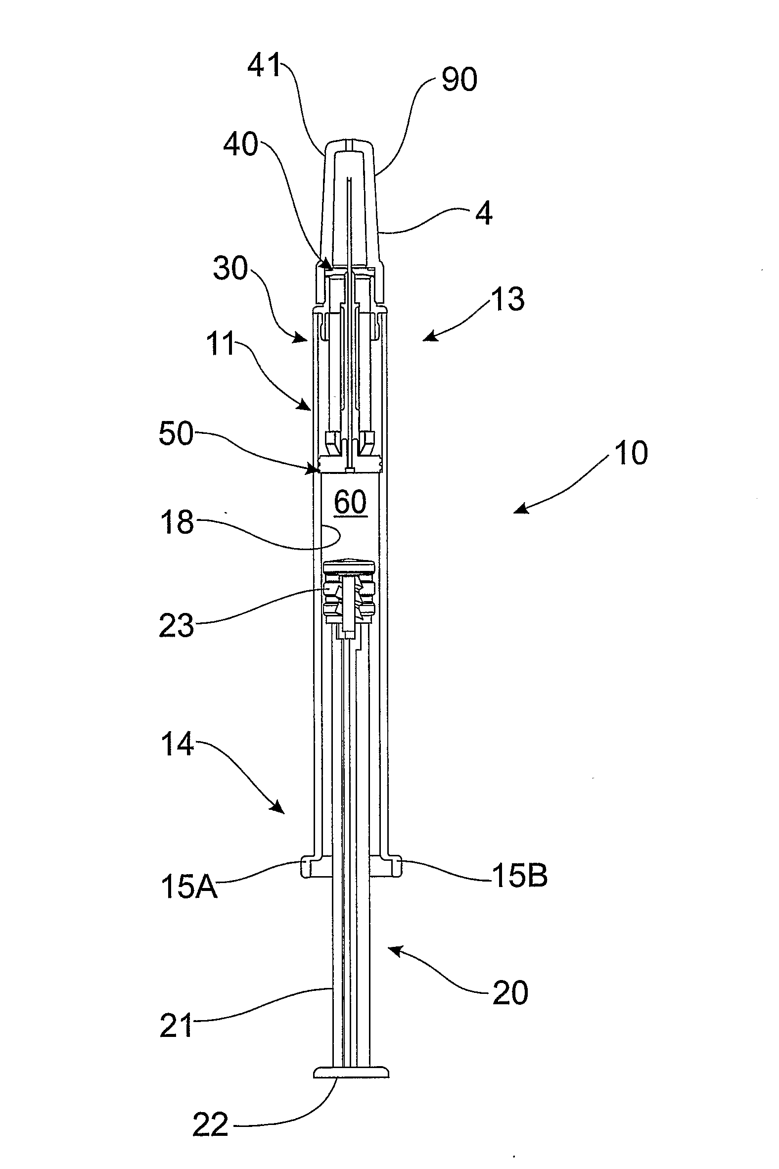
[0043]Referring to FIG. 1, syringe 10 comprises barrel 11, plunger 20, needle sheath 30, needle mount 40 and sheath seal 50. Barrel 11 comprises needle end 13 in which is located needle mount 40 comprising cannula 41. Protective cap 90 covers cannula 41 and is removed prior to use of syringe 10. Barrel 11 also comprises plunger end 14 at which are located paired finger grips 15A, 15B. Plunger seal 23, sheath seal 50 and inside wall 18 of barrel 11 define fluid space 60 inside barrel 11.

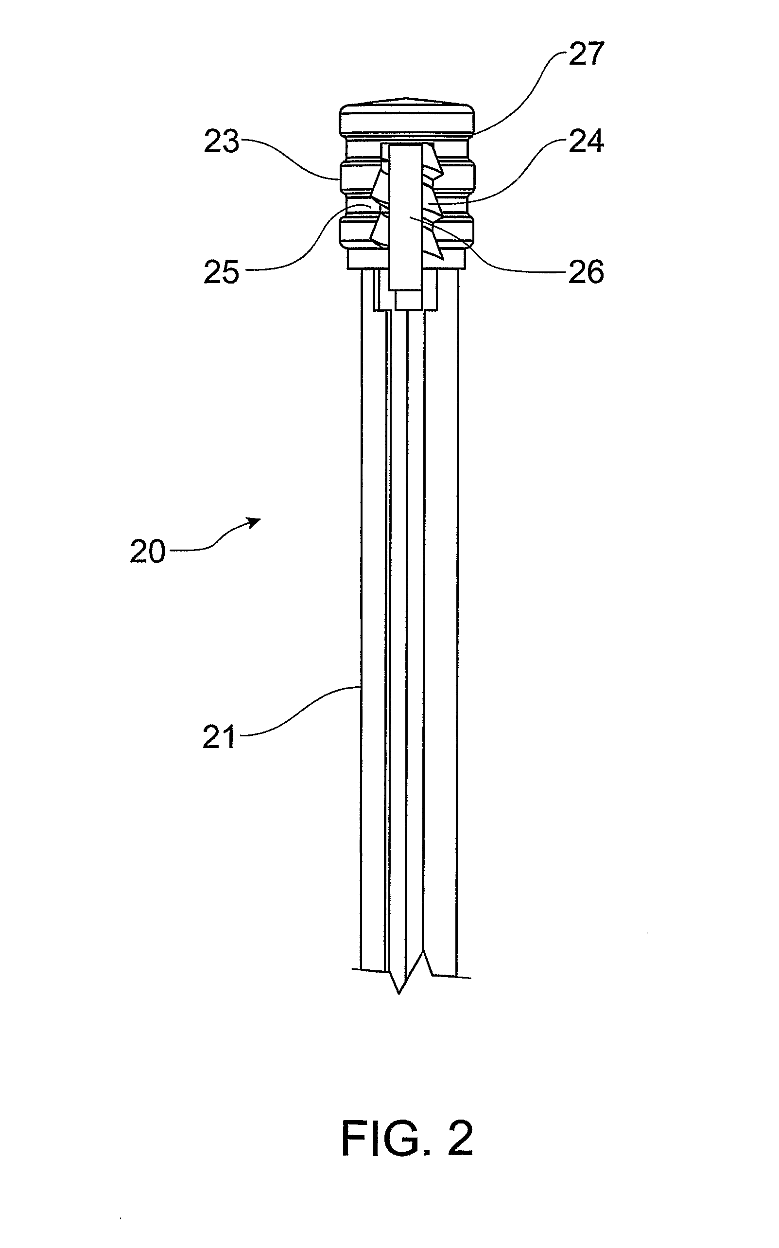
[0044]Referring to FIG. 1 and FIG. 2, plunger 20 comprises plunger rod 21 and button 22 operable by a user to facilitate plunger 20 depression. Plunger 20 further comprises plunger seal 23 having ribbed sealing member 27, which is coupled to plunger rod 21 by way of coupling member 24 on plunger rod 21 engaging complementary recess 25 in plunger seal 23. Coupling member 24 comprises bore 26 to receive cannula 41 as hereinafter described.

[0045]In this particular embodiment, coupling member 24 and compl...


PUM


Abstract

A syringe is provided which comprises a barrel (11) and a needle sheath (30) slidably located within the barrel, a plunger (20) with a plunger seal (23), a needle, a needle sheath (30) and a sheath seal (50), arranged so that depression of the plunger forces the needle sheath to move into a position where it covers or at least partly encloses the needle after delivery of fluid contents of the syringe. The needle sheath may be manually actuated or may be actuated by decompression of a spring. The syringe may further comprise a plunger disabling means operable to impede, prevent or otherwise hinder withdrawal of the plunger during or following depression of the plunger. The syringe may be a pre-filled syringe or a syringe which is filled by a user.

Description

FIELD OF THE INVENTION[0001]THIS INVENTION relates to syringes. More particularly, this invention relates to a syringe that comprises a sheath mechanism to prevent or minimize the risk of needlestick injury. This invention also relates to a syringe that comprises a sheath mechanism to prevent or minimize the risk of needlestick injury and a plunger disabling means to impede, prevent or otherwise hinder withdrawal of the plunger during or following depression of the plunger.BACKGROUND OF THE INVENTION[0002]The practice of sharing syringes without adequate sterilisation between successive users is a major contributor to the transfer of Human Immunodeficiency Virus (HIV) and Hepatitis with subsequent severe repercussions for the sufferer and at a high cost to society for supporting and providing medical attention to sufferers.[0003]In response to this problem, syringes have been developed with the aim of preventing syringe re-use.[0004]A particular problem associated with syringes is n...

Claims


Application Information

Patent Timeline
Patent Type & Authority Applications(United States)
IPC IPC(8): A61M5/32A61M5/315
CPCA61M5/326A61M5/502A61M2005/3265A61M2005/3247A61M2005/3261A61M5/508
Inventor JUDD, DAMIENKAAL, JOSEPH HERMESTHORLEY, CRAIG STEPHEN
Owner UN HOLDINGS LLC
Why Eureka
Try Eureka