Device For Blocking A Tendon Graft

a technology for tendon grafts and devices, applied in the field of devices for blocking tendon grafts, can solve the problems of tearing of tendon grafts and two structural elements, and achieve the effect of effective and irreversible blocking of wedges

Inactive Publication Date: 2008-04-24
KARL STORZ GMBH & CO KG
View PDF12 Cites 19 Cited by
  • Summary
  • Abstract
  • Description
  • Claims
  • Application Information

AI Technical Summary

Benefits of technology

[0019]This permits a particularly effective and irreversible blocking of the wedges.
[0020]This embodiment allows the operating surgeon initially to bring the assembly of tendon graft, wedge bodies and draw-threads into place, to check the fit, and then, by pulling on the draw-threads, to displace the wedges relative to one another, which displacement can be effected in steps by means of several locking teeth, so that, by gradually firmer pulling, a correspondingly firm blocking can be achieved. The catch arrangement ensures that this procedure is irreversible.

Problems solved by technology

A disadvantage of this design is that two structural elements are needed, that is to say the ball and the interference screw, in order to block the tendon graft.
As the interference screw is being screwed in, it is not possible to rule out the possibility of the tendon graft being damaged by the external thread, which can lead to tearing of the tendon graft when it is subjected to loading.

Method used


Image

  • Device For Blocking A Tendon Graft
  • Device For Blocking A Tendon Graft
  • Device For Blocking A Tendon Graft

Examples


Embodiment Construction

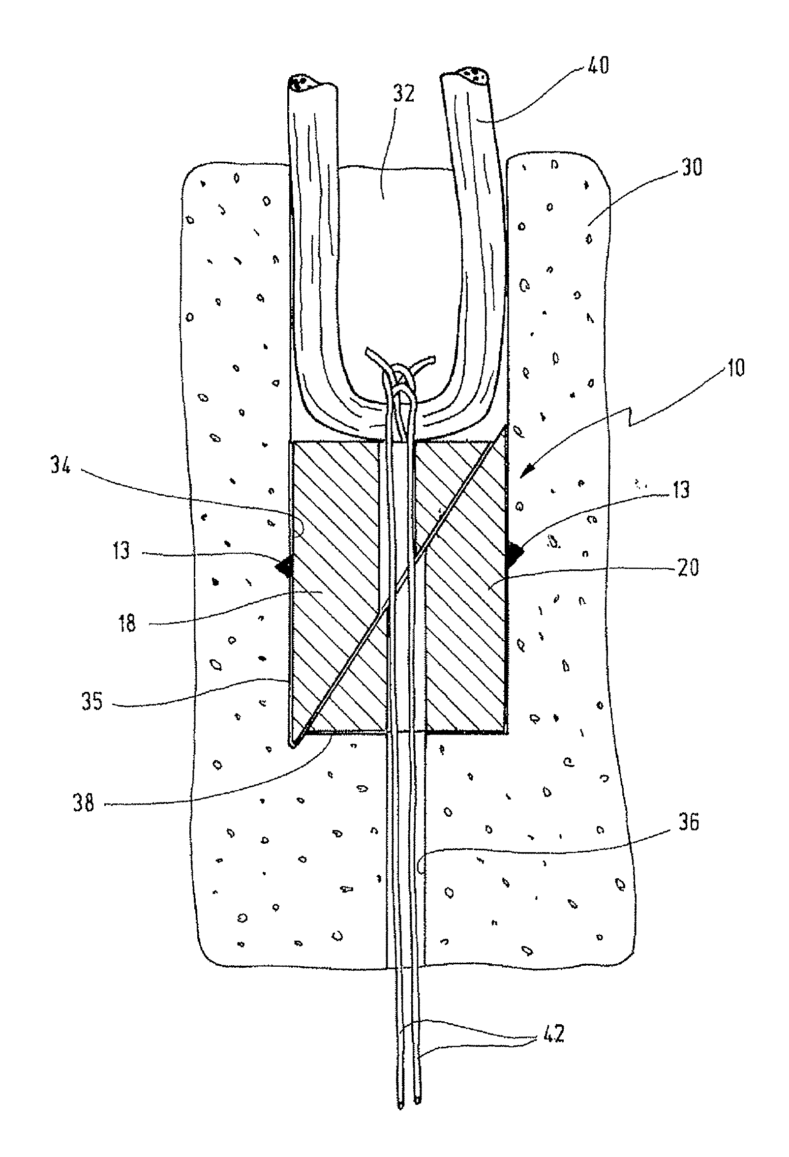
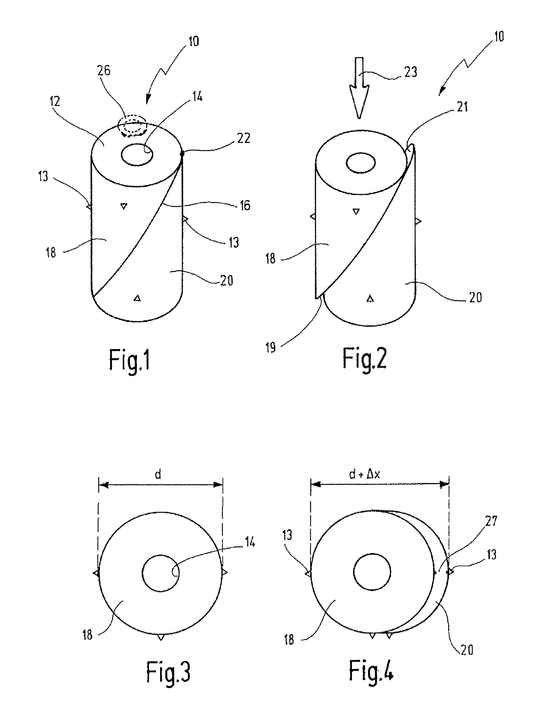
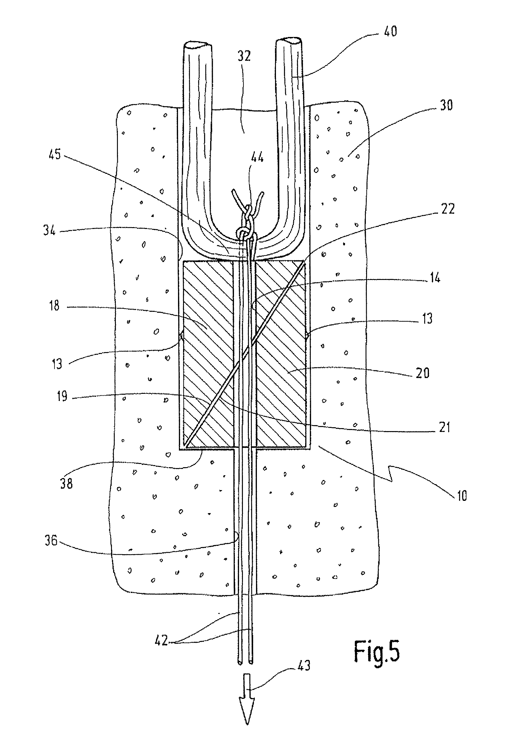
[0041]A radially expandable element shown in FIGS. 1 to 4 is designated generally by reference number 10.

[0042]The element 10 is composed of a cylindrical body 12 with a continuous bore 14 extending centrally through it.

[0043]The body 12 is divided by a diagonal oblique cut 16 into two wedge-shaped bodies 18 and 20. The surface of the cut at the same time defines the two mutually facing wedge surfaces 19 and 21 of the wedge-shaped bodies 18 and 20.

[0044]The oblique cut 16 is not entirely continuous, and instead the two wedge-shaped bodies 18 and 20 are still connected to one another via a more or less punctiform predetermined break point 22, so that the body 12 is held in the position shown in FIG. 1, i.e. the two wedge-shaped bodies 18 and 20 do not come apart from one another. On its outside, the body 12 is provided with projections in the form of claws 13 that protrude radially from it. It will be seen from the plan view in FIG. 3 that the body has a diameter d.

[0045]When a force...


PUM


Abstract

A device serves for blocking a tendon graft in a drilled hole. An element is connected to said tendon graft which can be expanded radially. The element has a cylindrical body which is divided by an oblique cut into two wedge-shaped bodies initially connected to one another via a predetermined break point.

Description

BACKGROUND OF THE INVENTION[0001]The invention relates to a device for blocking a tendon graft in a drilled hole in a bone, the drilled hole having a first portion with a first diameter for receiving the tendon graft, said first portion being adjoined by a second portion of smaller diameter through which pulling threads connected to the tendon graft extend as far as the outer face of the bone.[0002]Tendon grafts of this kind are used in particular for replacing the anterior or posterior cruciate ligament of the knee joint in cases of injury. The operating technique generally used is described in detail in Strobel, Michael: Arthroskopische Chirurgie, Springer, 1998, in Kapitel 2, Kniegelenk, pages 438, 459.[0003]For example, in order to anchor a tendon graft in the femur, a drilled hole is formed in the latter, from the direction of the knee joint, said drilled hole having a first portion with a first diameter for receiving the tendon graft. This first portion is adjoined by a second...

Claims


Application Information

Patent Timeline
Patent Type & Authority Applications(United States)
IPC IPC(8): A61F2/08
CPCA61B17/0401A61B2017/0403A61B2017/042A61B2017/0427A61F2002/0882A61F2/0811A61F2002/0829A61F2002/0852A61B2017/0458
Inventor STROBEL, MICHAEL J.WEILER, ANDREASBERBERICH, SASCHA
Owner KARL STORZ GMBH & CO KG
Why Eureka
Try Eureka