
Cutting machine

A technology of cutting machines and cutting knives, applied in the field of cutting machines, can solve problems such as hindering cutting knives, reducing cutting efficiency, dulling, etc., and achieve the effect of reducing replacement operations

Active Publication Date: 2013-05-08
SHIMA SEIKI MFG LTD
View PDF5 Cites 14 Cited by
  • Summary
  • Abstract
  • Description
  • Claims
  • Application Information

AI Technical Summary

Problems solved by technology

Adhesion near the edge of the knife prevents the cutting knife from dulling, etc. Although the life of the cutting knife relative to wear is prolonged, it makes cutting difficult
Cutting has to be stopped in order to remove the attachment from the cutting blade, which is troublesome and reduces the efficiency of cutting

Method used


Image

  • Cutting machine
  • Cutting machine
  • Cutting machine

Examples


Embodiment Construction

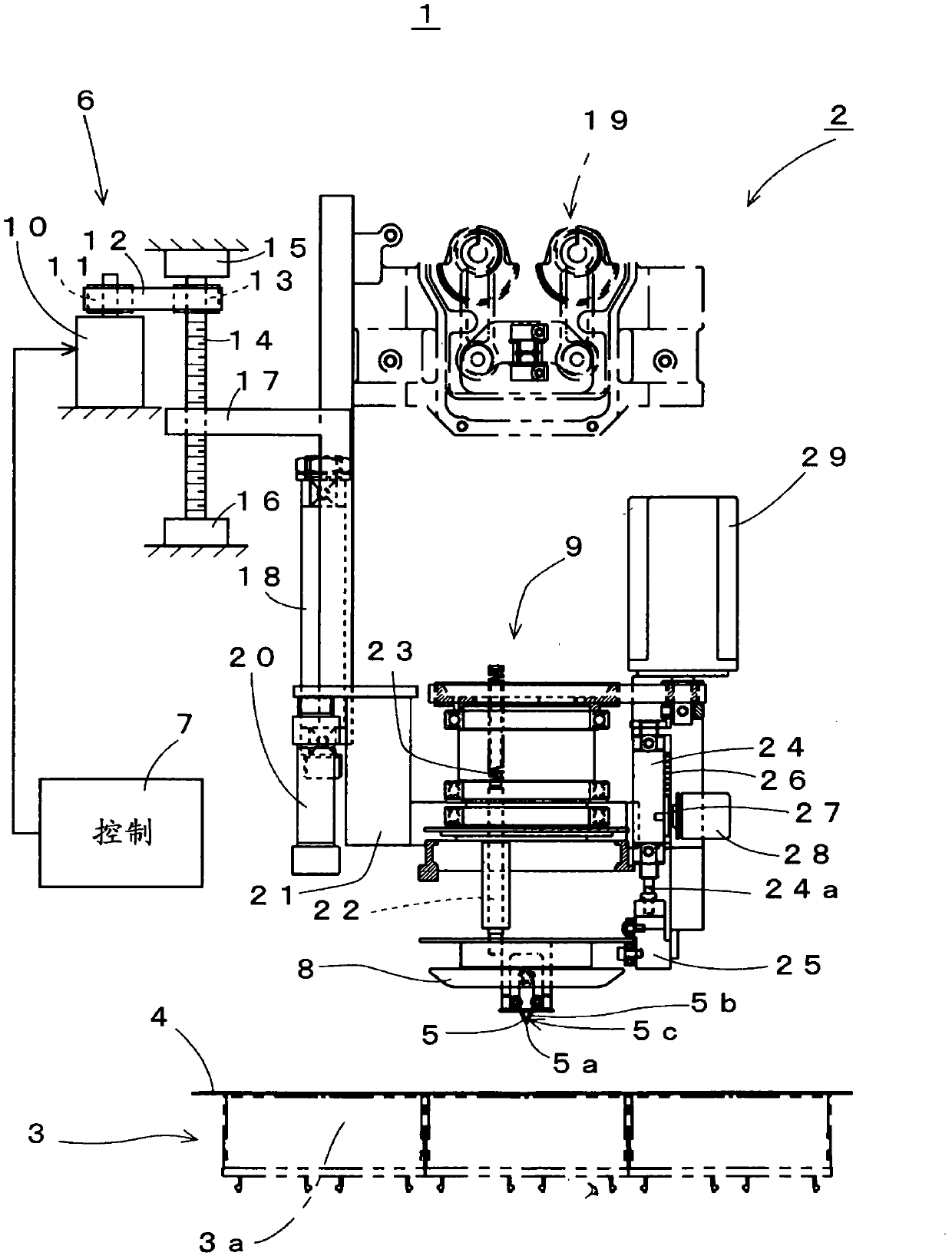
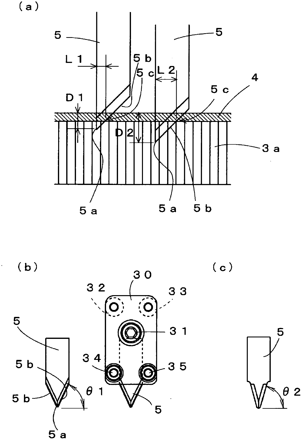
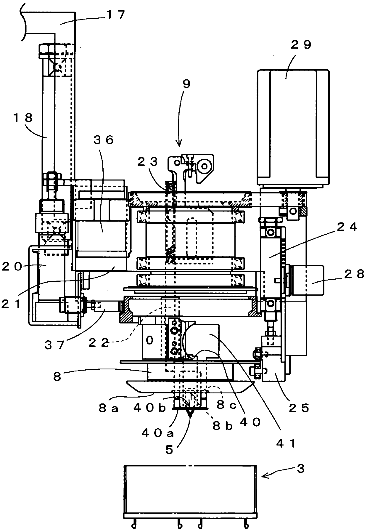
[0050]Below, use Figure 1 to Figure 7 An example of the present invention will be described. In the description of each figure, reference numerals that do not exist in the figure but exist in the previously described drawings may be used for description, or the same parts as those shown in the previously described drawings are given the same Reference numerals are used to omit repeated explanations.

[0051] 【Example】

[0052] figure 1 The schematic structure of the main part of the cutting machine 1 which is one embodiment of this invention, especially the cutting head 2 is shown. The basic structures of the cutting machine 1 and the cutting head 2 are the same as those described in Patent Document 2. That is, the cutting head 2 cuts while moving along the XY plane on the surface of the sheet 4 placed on the horizontal table 3 . The table 3 is lined with bristle brushes 3a and formed of bristles standing upright from below, and includes an air-permeable surface capable ...


PUM


Abstract

The invention provides a cutting machine which may prolongs service life of a cutting knife in a simple structure and can reduce replacing work of the cutting knife. Cutting a sheet-like article is performed in an action position (5c) that becomes a part of a knife edge (5b) in a state of stabbing an oblique cutting knife (5) to the sheet-like article from above. A cutting knife elevation mechanism (6) is provided for elevating and moving the oblique cutting knife. Even if service life of the action position (5c) reaches the service life of the knife edge (5b), the action position can be switched to other action positions (5c) for continuous cutting. Since the knife edge (5b) is oblique, a distance between a reference position of a cutting head (2) and the action position (5c) varies according to the height of the action position (5c) relative to a knife tip (5a). Concerning the variation, control of the cutting head (2) is performed by modifying cutting data by the control portion (7), and thus cutting with no error can be performed.

Description

technical field [0001] The present invention relates to a cutting machine for cutting sheets, especially hard industrial materials including carbon fiber, according to preset data. Background technique [0002] Conventionally, the following technology has been proposed: in order to cut prepregs or various plastic sheets into arbitrary shapes, which are intermediate raw materials for molding fiber-reinforced plastics (FRP) containing carbon fibers, etc., using a sheet cutting device (such as Refer to Patent Document 1). In this sheet cutting device, a sheet is spread out on a flat table, the protruding end of a cutting blade having an obliquely formed edge is brought into contact with it, and the cutting blade is moved in a direction in which the blade is inclined relative to the sheet. Move relative to cut off. If the cutting of hard industrial materials is continued, the part of the cutting edge of the blade wears out, the blade becomes blunt, and edge curling or chipping...

Claims


Application Information

Patent Timeline
IPC IPC(8): B26D5/00B26D7/26B26D7/08
CPCB26F1/382B26D7/12B26D7/18B26D7/025B26D5/02B26D7/26B26D1/02B26D7/2628
Inventor 有北礼治
Owner SHIMA SEIKI MFG LTD
Learn More