

Ball Robot
a robot and ball technology, applied in the field of autonomous or controlled robot balls, can solve the problems of inability to return to the operational position, insufficient robustness to sustain, and major drawbacks of ball robots of shell drive type, and achieve good traversability
- Summary
- Abstract
- Description
- Claims
- Application Information
AI Technical Summary
Benefits of technology
Problems solved by technology
Method used
Image

Examples
Embodiment Construction
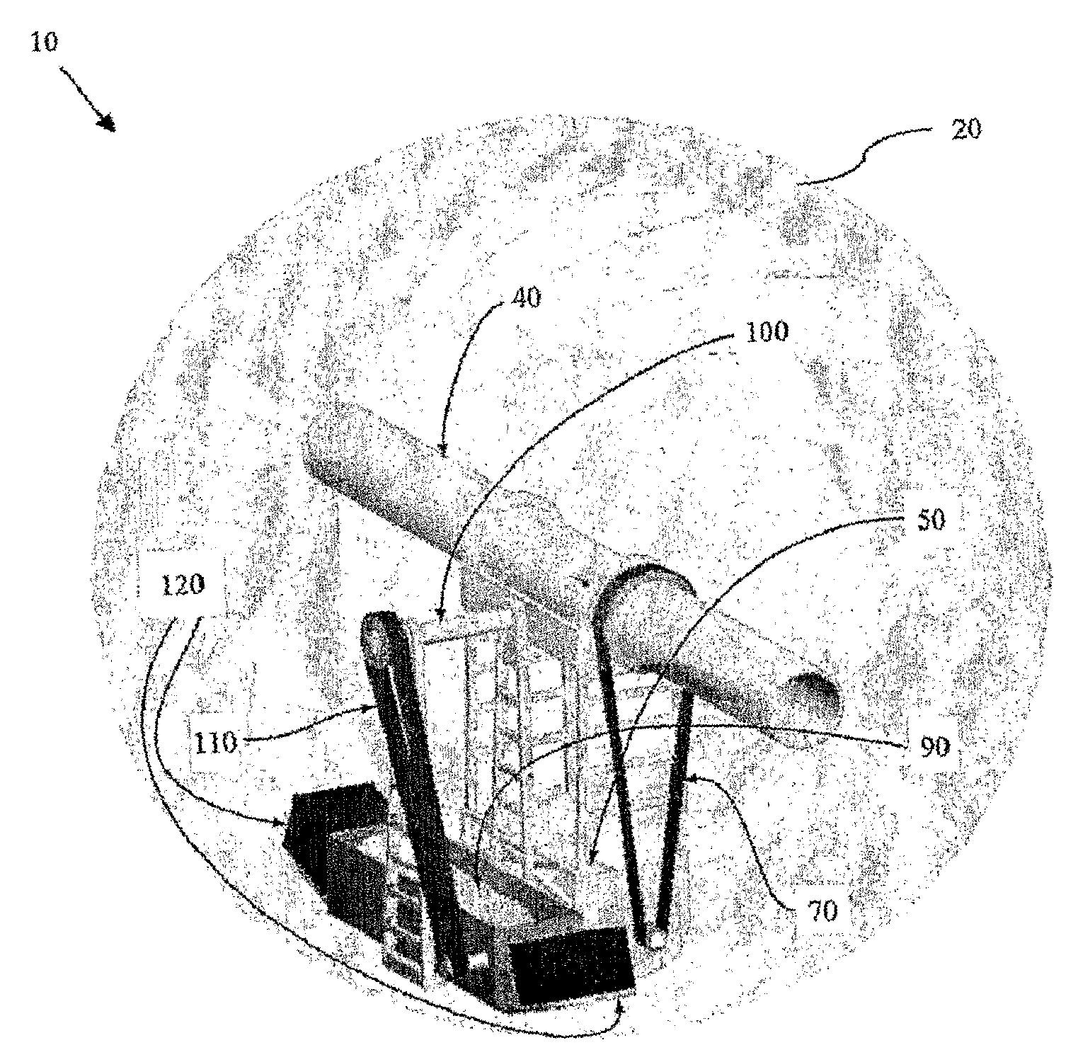
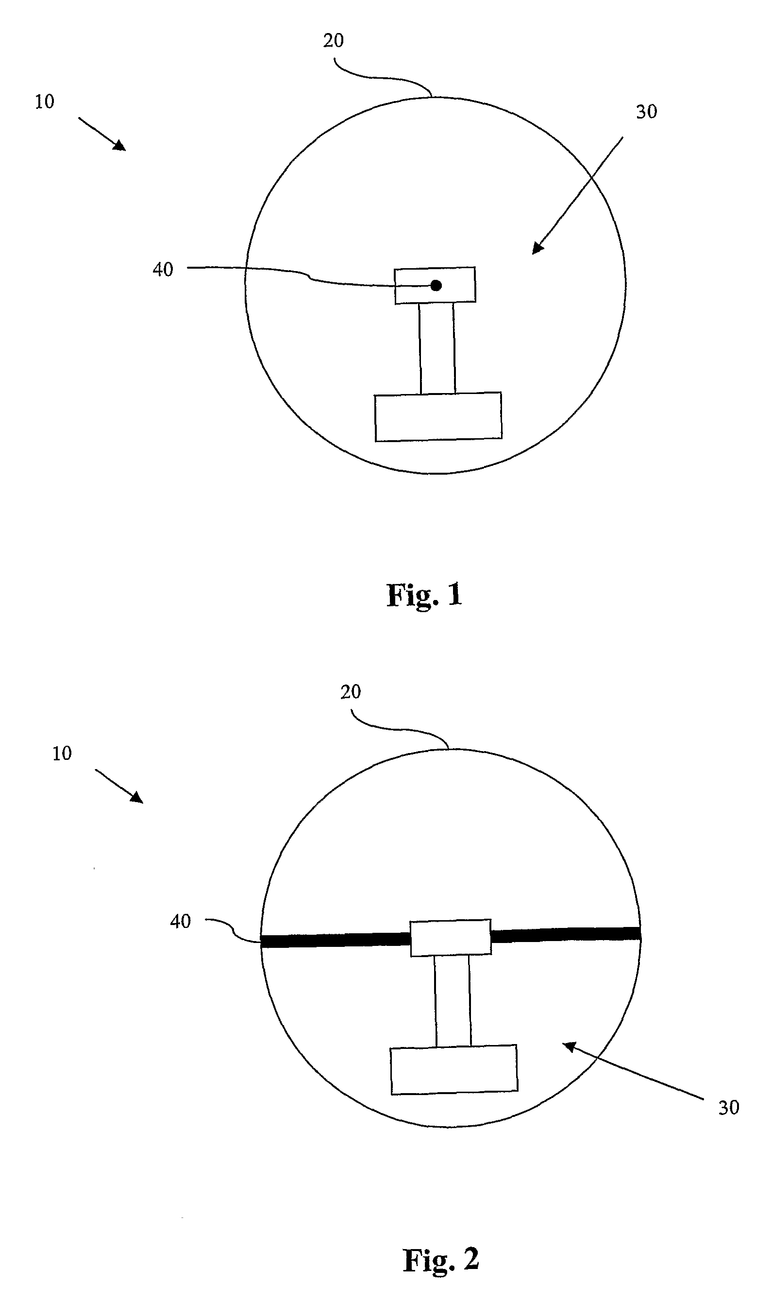
[0047] A ball robot of the ball robot system according to the present invention comprises one or more of the following features: [0048] spherical or nearly spherical encapsulating shell with a hollow main axis; [0049] a mechanical driving unit situated inside the shell; [0050] a battery power supply system inside or outside the shell; [0051] a wireless communication unit including one or several antennas for transmitting and receiving data to and from one or several base stations. [0052] a computer processing unit for storing, receiving and transmitting data, [0053] a house keeping sensor unit for sensing, collecting and transmitting measurable physical quantities / changes inside the shell. [0054] a sensor system unit for sensing, collecting and transmitting measurable physical quantities / changes on or outside the shell. [0055] an actuator system unit for controlling the mechanical driving device and other actuators such as loudspeakers, video projectors, and other passive and active...
PUM
 Abstract
Description
Claims
Application Information