
Intelligent Bolt Sensor and Calibration Method

An intelligent, sensor-based technology, applied in instruments, signal transmission systems, calibration/testing of force/torque/power measuring instruments, etc., can solve problems such as difficulty in meter reading, difficulty in meter calibration of bolt sensors, etc., and achieve sudden interference And the effect of sensitivity improvement, automatic filtering of errors and false information, and good stabilization function

Active Publication Date: 2015-12-02
山东科德电子有限公司
View PDF3 Cites 0 Cited by
  • Summary
  • Abstract
  • Description
  • Claims
  • Application Information

AI Technical Summary

Problems solved by technology

[0004] The purpose of the present invention is to solve the problems of difficult calibration and meter reading of the anchor sensor, improve it, and design an intelligent anchor sensor

Method used


Image

  • Intelligent Bolt Sensor and Calibration Method
  • Intelligent Bolt Sensor and Calibration Method
  • Intelligent Bolt Sensor and Calibration Method

Examples


Embodiment Construction

[0031] The technical scheme of the intelligent anchor sensor is further described with reference to the accompanying drawings.

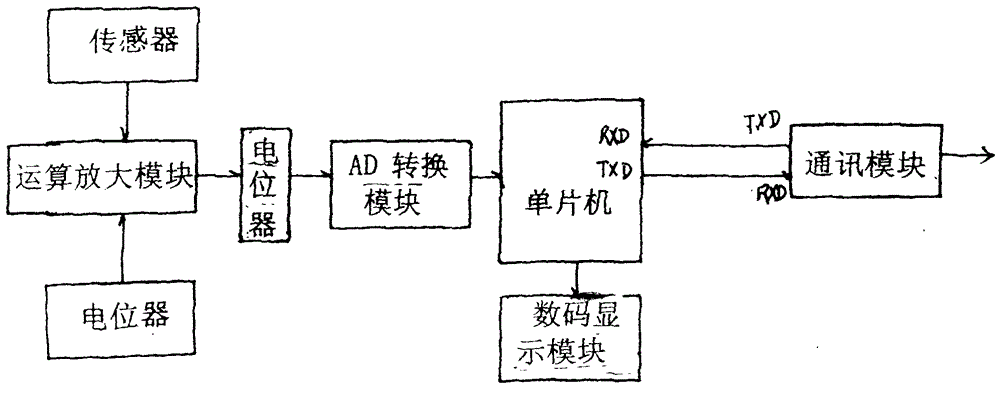
[0032] figure 1 It is the schematic block diagram of the circuit of the existing bolt sensor. It can be seen from the figure that it is composed of a single chip microcomputer, a communication module RSM3485, an AD conversion module, a digital display module, an operational amplifier, a resistance bridge type stress sensor and a calibration potentiometer.

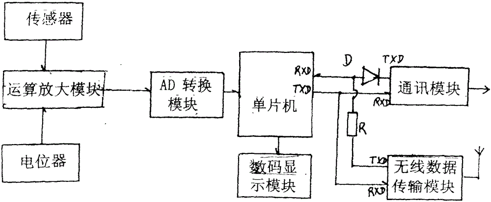
[0033] figure 2 It is a block diagram of the circuit principle of the embodiment of the intelligent anchor sensor of the present invention. It can be seen from the figure that it is composed of a single-chip microcomputer, a communication module RSM3485, an AD conversion module, a digital display module, an operational amplifier OPO7BP, and a resistance bridge stress sensor. ; It also includes a wireless data transmission module; the wireless data transmission module adopts the highly integrated...


PUM


Abstract

The invention discloses an intelligent anchor rod sensor and a calibrating method thereof. The intelligent anchor rod sensor is composed of a singlechip microcomputer, a communication module RSM3485, an AD (Analog to Digital) conversion module, a digital display module, an operation amplifier, a resistance bridge type stress sensor and a wireless data transmission module, wherein the wireless data transmission module is embedded into a circuit between the singlechip microcomputer and the communication module RSM3485. When the intelligent anchor rod sensor is used, a miner light is prevented from being used for awakening, and the collection can be completed automatically as long as a worker walks through a side place about 10-15 meters away by taking a collector. An automatic calibration function is fulfilled through a software-simulation potentionmeter, and the precision is high up to more than grade 0.5.

Description

technical field [0001] The invention relates to a coal mine support bolt monitoring instrument. Background technique [0002] At present, in coal mine support, it is necessary to monitor the condition of support bolts for production safety. The bearing stress of the end-anchored metal anchor is reflected as the force of the anchor bolt and the pallet. When monitoring, install a resistance bridge stress sensor with a through hole between the nut of the anchor rod and the tray to measure the force of the anchor rod. The stress of the anchor rod is not the anchoring force of the anchor rod. The stress of the anchor rod reflects the The support capacity of the anchor to the roof. The anchor rod stress sensor is like this. Firstly, an elastic element is designed. When the force acts on the elastic element, the elastic body deforms, and 900 equal parts are pasted on the elastic body wall by 4 single-bridge strain gauges and 4 single-bridge strain gauges. Form a resistance full ...

Claims


Application Information

Patent Timeline
Patent Type & Authority Patents(China)
IPC IPC(8): G01L1/22G08C17/02G01L25/00
Inventor 孟鸿鑫汤元信邱文明彭慧
Owner 山东科德电子有限公司
Learn More