
Holding fixture for all types of drilling concerning woodworking

a technology for holding fixtures and woodworking, applied in the field of drilling operations, can solve the problems of time-consuming subsequent operations, easy damage of drill bits, and damage to workpieces, and achieve the effect of being easily adjusted

Inactive Publication Date: 2008-05-01
CHIANG VANCE
View PDF10 Cites 37 Cited by
  • Summary
  • Abstract
  • Description
  • Claims
  • Application Information

AI Technical Summary

Benefits of technology

[0005]The main objective of the invention is to provide a holding fixture suitable for use in all types of drilling concerning woodworking that can be readily adjusted according to the various shapes and sizes of the workpieces to best guide the drilling operations.

Problems solved by technology

In woodworking, angularly drilled holes are important for joining workpieces, but to prevent the holes from being excessively drilled, leading to damaged workpieces, the drill bit also needs to be placed at an angle.
However, the modules are designed fixed during drilling, and as a result, subsequent operations are time-consuming, and the drill bit is easily damaged.
Though such design can solve the disadvantages found in the prior art described above, the drilling operation is still not entirely convenient because only one of the guide rods can be adjusted horizontally, the height of the workpiece cannot be adjusted, and the guide sleeve is fixed in the through-hole of the guide rods, which impedes the cleaning of wooden chips from the guide rods.
Furthermore, the holding fixture disclosed in U.S. Pat. Nos. 5,791,835 and 4,955,766 can only hold workpieces with flat rectangular surfaces, workpieces in the shape of sticks, rods, and especially cylinders are difficult to hold, which is a major obstacle in the drilling process.

Method used


Image

  • Holding fixture for all types of drilling concerning woodworking
  • Holding fixture for all types of drilling concerning woodworking
  • Holding fixture for all types of drilling concerning woodworking

Examples


Embodiment Construction

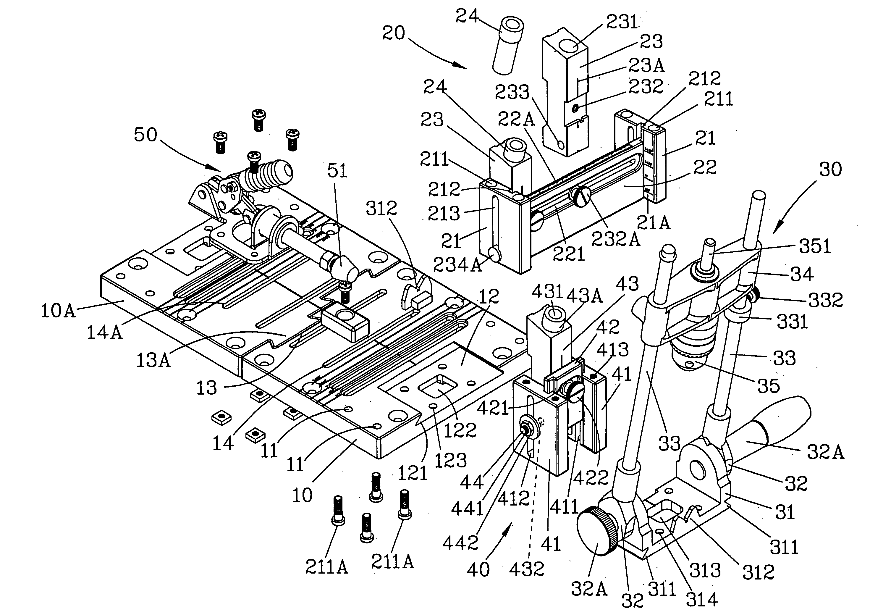
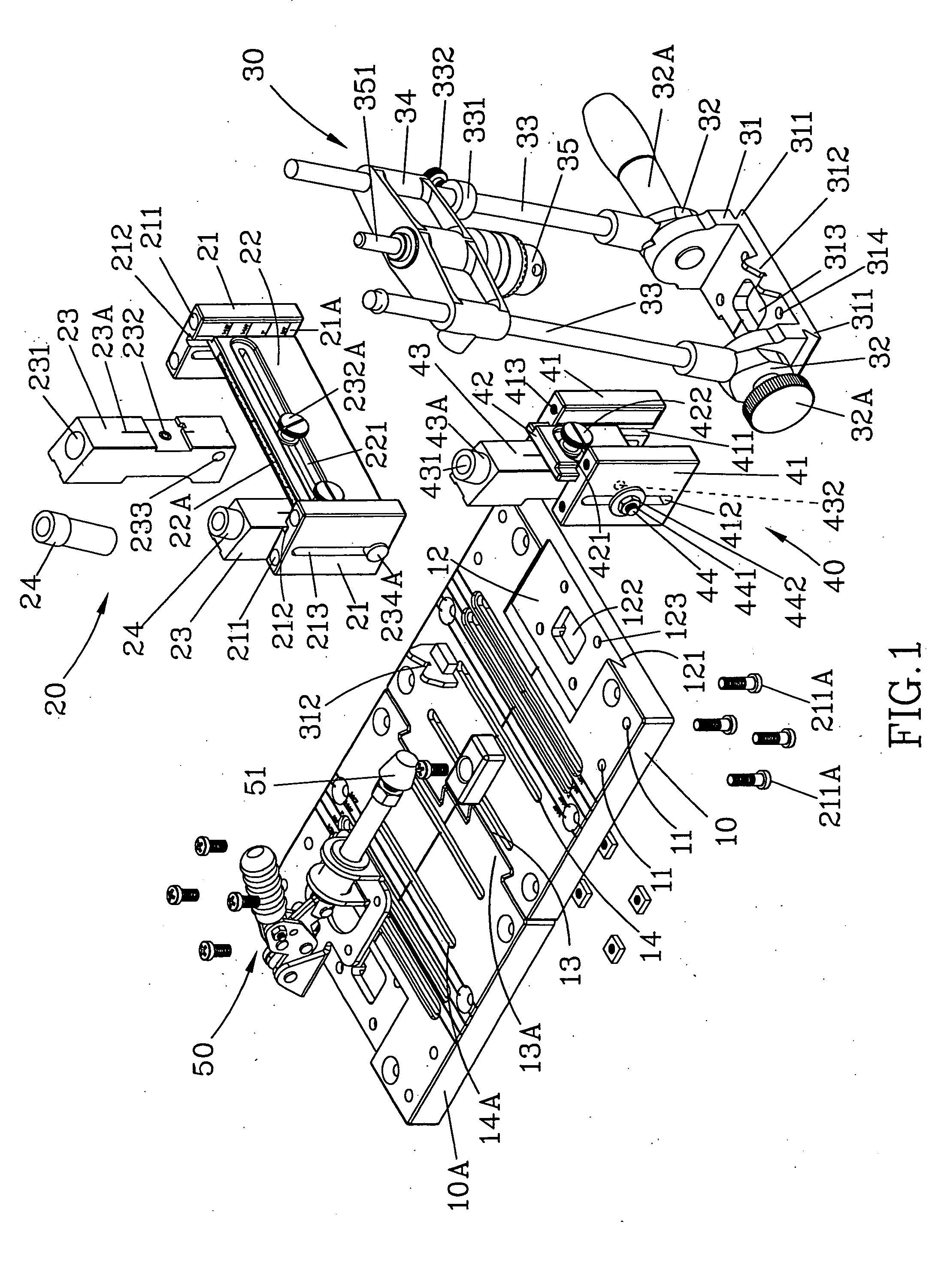
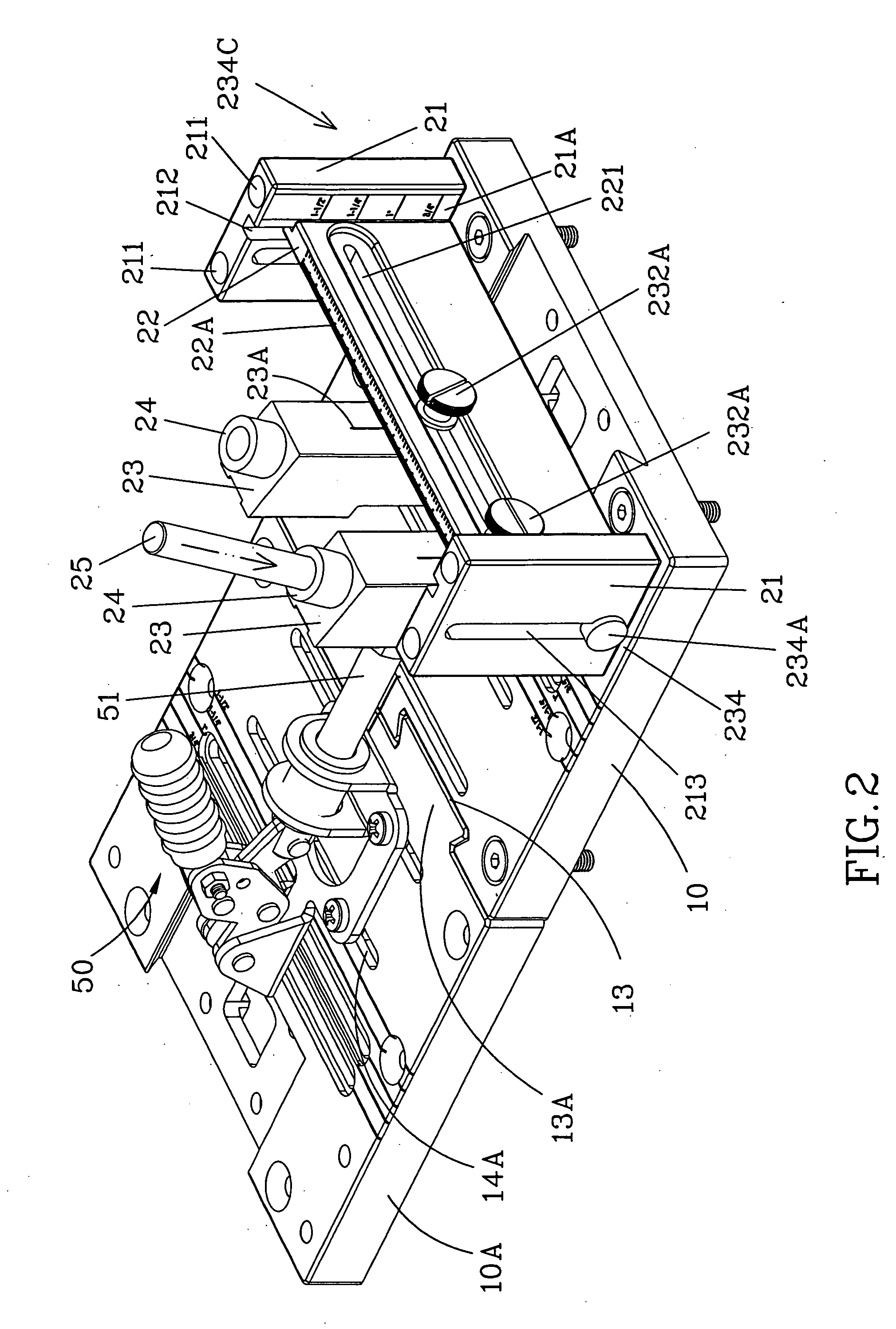
[0021]The invention proposes a holding fixture for all types of drilling that concerns woodworking, as shown in FIG. 1, it comprises two flat worktables 10, a longitude-transverse adjustment module 20, an angle adjustment module 30, a height adjustment module 40, and a clamp member 50; wherein:

[0022]said flat worktables 10 and 10 A having a set of horizontal front alignment openings 11 on the left and the right edges, and a horizontal front recess 12 indented at center, said recess 12 has angularly indented symmetrical dovetail-shaped troughs 121 on the left and the right lateral sides, respectively, a rectangular indentation 122 being indented downwardly at center and four alignment openings 123 being disposed on its four corners; the rear end of said flat worktable also has a set of dovetailing portions 13 and 13A, said dovetailing portions 13 and 13A being symmetrical in the protruding and indented portions, as indicated in FIG. 1, two said flat worktables 10 and 10A dovetail int...


PUM

PropertyMeasurementUnit
Sizeaaaaaaaaaa

Abstract

The invention proposes a holding fixture for use in all types of drilling concerning woodworking, comprised of at least one flat worktable having a set of dovetailing portions at the rear end for two flat worktables to dock together horizontally; a longitude-transverse adjustment module vertically arranged on the flat worktable, which secures the guide members for guiding the adjustments of height or latitude during drilling; an angle adjustment module being aligned at the front edge of said flat worktable, which guides the drilling operation on workpieces attached thereof; a height adjustment module vertically arranged at the front edge of flat worktable; a clamp member being secured on the flat worktable for securing workpieces to be worked on; as a result, the holding fixture is suitable for use in guiding the drilling operation on workpiece of all shapes and sizes.

Description

FIELD OF THE INVENTION [0001]The invention relates to the operation of drilling in DIY woodworking. More particularly, it is related to a holding fixture that is suitable for use in all types of drilling concerning woodworking.DESCRIPTION OF PRIOR ART [0002]In woodworking, angularly drilled holes are important for joining workpieces, but to prevent the holes from being excessively drilled, leading to damaged workpieces, the drill bit also needs to be placed at an angle. The angular holes are fitted with screws for securing more components. In the prior arts related to the drilling of angular holes, for example, in U.S. Pat. No. 4,955,766, it is necessary to draw precise guidelines and then make puncture holes prior to carrying out angular drilling with the use of relevant modules. However, the modules are designed fixed during drilling, and as a result, subsequent operations are time-consuming, and the drill bit is easily damaged.[0003]Moreover, as of U.S. Pat. No. 5,791,835 “HOLDIN...

Claims


Application Information

Patent Timeline
IPC IPC(8): B27M3/00B27L9/00B27C9/00B27L3/00B27L5/00
CPCB23B47/287B23B2260/088B23B2247/12
Inventor CHIANG, VANCE
Owner CHIANG VANCE
Learn More