
Multi-Function Workbench with Wireless controls

Inactive Publication Date: 2008-05-01
BRADLEY ANTHONY A
View PDF42 Cites 10 Cited by
  • Summary
  • Abstract
  • Description
  • Claims
  • Application Information

AI Technical Summary

Benefits of technology

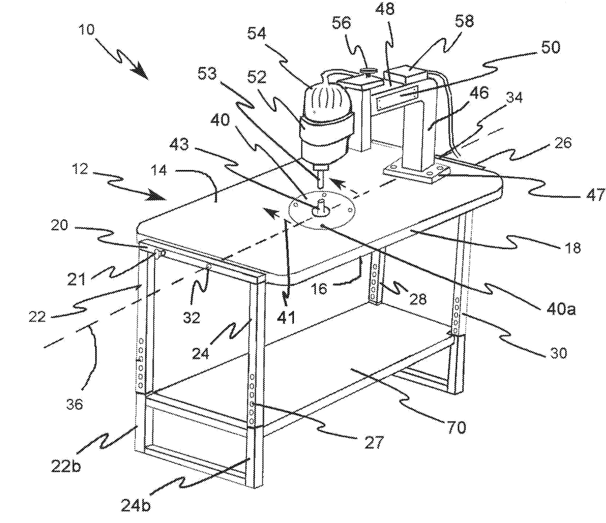
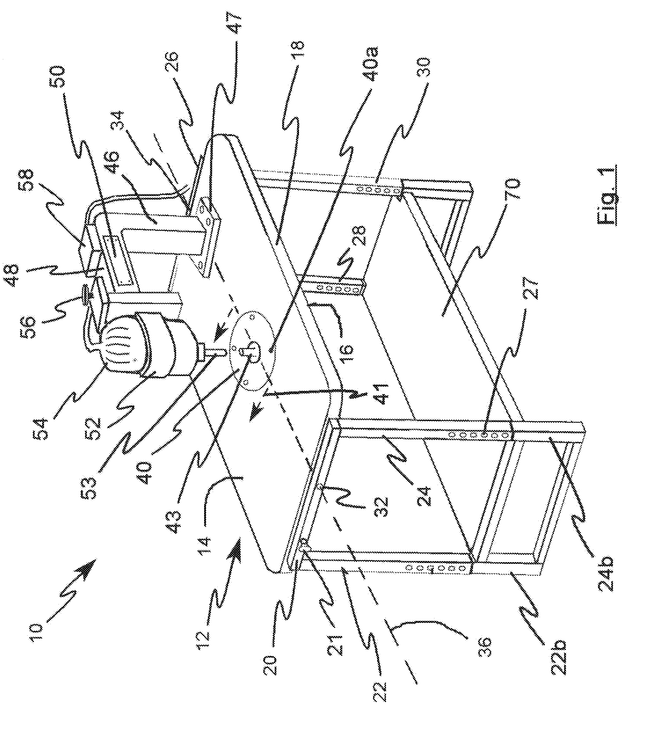
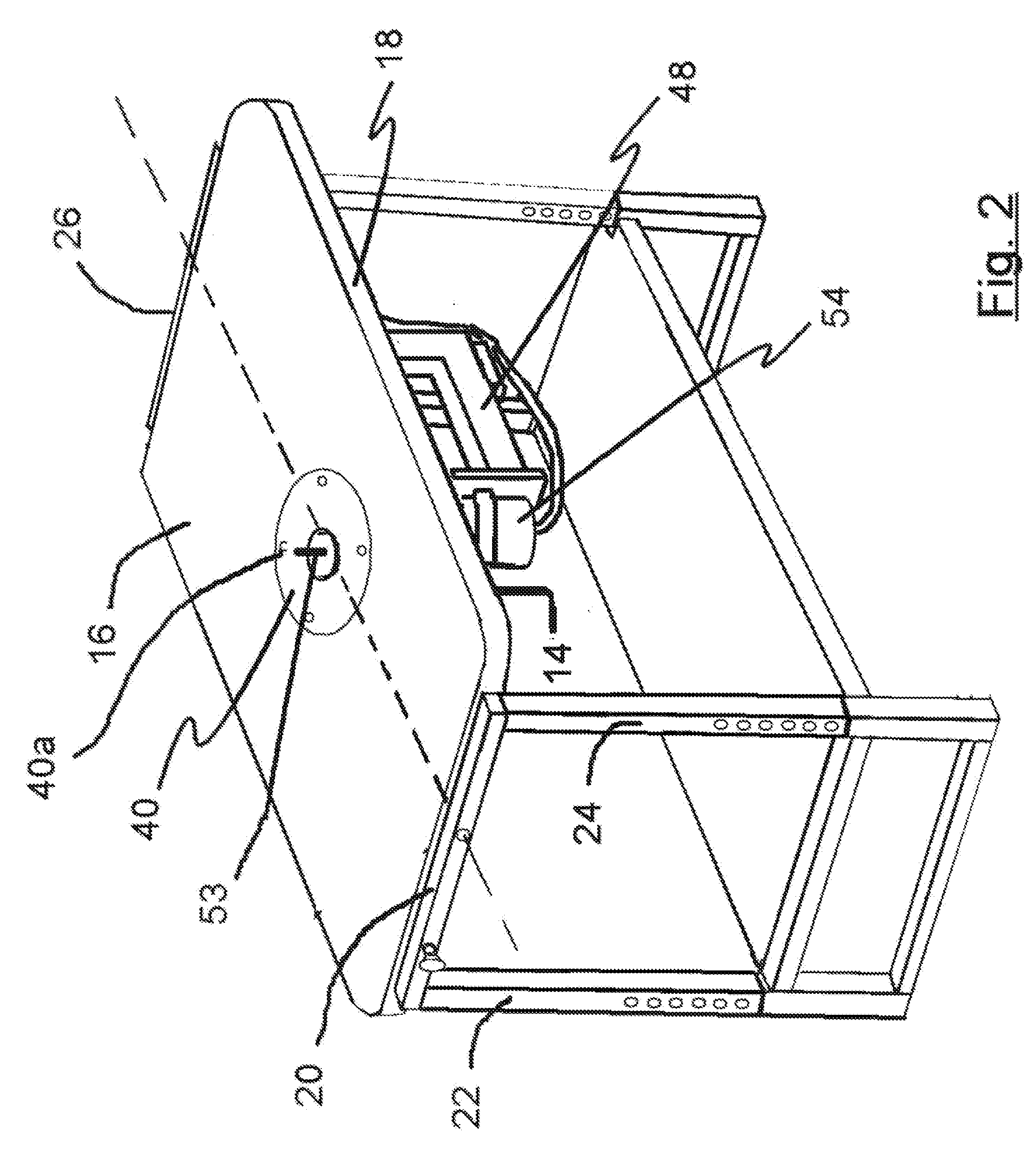
[0009]Broadly speaking, a principle object of the present invention is to provide a combined routing and shaping tool comprising a work bench, a motor support structure associated with a motor wherein the workbench may be placed in plurality of work positions so that the tool may be used as both an over arm pin router and an under table router / shaper for precision machining of a work piece without requiring the motor unit to be repositioned.
[0011]Still another object of the invention is to provide for an adjustable motor support structure that has a low vertical profile and provides for adjusting the distance between a motor associated with the support structure and a work surface.
[0013]Another object of the invention is to provide a work bench configured to simultaneously receive a plurality of work tools on a plurality of work surfaces thereby maximizing work space utilization efficiency.

Problems solved by technology

One example of such prior art designs is described in U.S. Pat. No. 1,718,275 issued to R. L. Carter. Such prior art device are generally constructed from massive cast iron components making them relatively expensive and heavy, and thus, relatively awkward to use.
Additionally, such prior devices comprise support structures that are not optimized for pin router application.
The Schumacher workbench also has several design issues that limit its usefulness for use as a pin router.
Thus, the work piece cannot easily be moved across the entire surface of such a work surface as the work piece will come in contact with the frame support.
Such devices often comprise lifts, jacks and adjustment mechanisms for moving the router apparatus, but such systems still do not provide sufficient versatility or maximize work shop space utilization effectively.
Many prior art routing plunge mechanisms have been developed to perform such functions; however, such mechanisms typically have an undesirably large vertical profile.
Such large vertical profile greatly complicates or makes it impossible to flip the top to a second configuration where the systems become an under table router / shaper.
First, a user often becomes preoccupied with the foot pedal location taking attention away from the task at hand.
Thus, a user may feel like he has been standing on one leg the entire time he is using the system as that leg becomes fatigued faster than the leg operating the foot pedal.

Method used


Image

  • Multi-Function Workbench with Wireless controls
  • Multi-Function Workbench with Wireless controls
  • Multi-Function Workbench with Wireless controls

Examples


Embodiment Construction

[0053]Reference now will be made in detail to the embodiments of the invention, one or more examples of which are set forth below. Each example is provided by way of explanation of the invention, not limitation of the invention. In fact, it will be apparent to those skilled in the art that various modifications and variations can be made in the present invention without departing from the scope or spirit of the invention. For instance, features illustrated or described as part of one embodiment can be used on another embodiment to yield a still further embodiment. Thus, it is intended that the present invention covers such modifications and variations as come within the scope of the appended claims and their equivalents. Other objects, features, and aspects of the present invention are disclosed in or may be determined from the following detailed description. Repeat use of reference characters is intended to represent same or analogous features, elements or steps. It is to be unders...


PUM


Abstract

The present invention relates to a workbench apparatus for routing and shaping work pieces. The workbench includes a top comprising two opposed faces with a motor support structure associated with one face for holding a motor configured to receive one of a router element and a shaping element. The top is pivotally associated with a top support structure thereby allowing the workbench to be selectably positioned in at least one of two work mode configurations. The top dimensions and support structure configuration is selected so that a work piece may be moved across the top surface without interference for the support structure. The motor support structure is configured for a minimum vertical profile while providing motor movement relative to the work piece. The system may further comprise wireless technology for controlling the motor movement. The workbench apparatus without the routing support structure can be used for attaching and storing a plurality of devices.

Description

TECHNICAL FIELD OF THE INVENTION[0001]The present invention relates to a workbench configured for routing and shaping work pieces and the efficient storage of work tools.BACKGROUND OF THE INVENTION[0002]Various types of workbenches and work support structures are known in the art of shaping and routing work pieces using tools associated with a motor. Many prior art configurations provide the ability for detaching the motor apparatus from the workbench and reattaching the motor apparatus at a second location thereby providing multiple functions. One example of such prior art designs is described in U.S. Pat. No. 1,718,275 issued to R. L. Carter. Such prior art device are generally constructed from massive cast iron components making them relatively expensive and heavy, and thus, relatively awkward to use. Additionally, such prior devices comprise support structures that are not optimized for pin router application.[0003]In more recent years new workbench configurations have been deve...

Claims


Application Information

Patent Timeline
IPC IPC(8): B27C5/00B25H1/00
CPCB27C5/02B27C9/02B27C5/10
Inventor BRADLEY, ANTHONY A.
Owner BRADLEY ANTHONY A
Learn More