Vehicle fender panel mounting structure

a technology for mounting structures and fender panels, which is applied in the direction of roofs, bumpers, pedestrian/occupant safety arrangements, etc., can solve the problems of insufficient reaction force and failure to achieve, and achieve good protection capability

Inactive Publication Date: 2008-05-01
TOYOTA JIDOSHA KK
View PDF1 Cites 12 Cited by
  • Summary
  • Abstract
  • Description
  • Claims
  • Application Information

AI Technical Summary

Benefits of technology

[0008]The present invention provides a vehicle fender panel mounting structure in which good protection capability may be obtained for pedestrians, even when the break line portion between th

Problems solved by technology

Whilst it may be considered that the above technology enables an increase in the pedestrian protection capabilities to be achieved, however, there are instances in which this is not successful due to the design of the vehicle.
If the above conventional technology is applied to a vehicle adopting such a design, when an impact object impacts in the

Method used


Image

  • Vehicle fender panel mounting structure
  • Vehicle fender panel mounting structure
  • Vehicle fender panel mounting structure

Examples


first exemplary embodiment

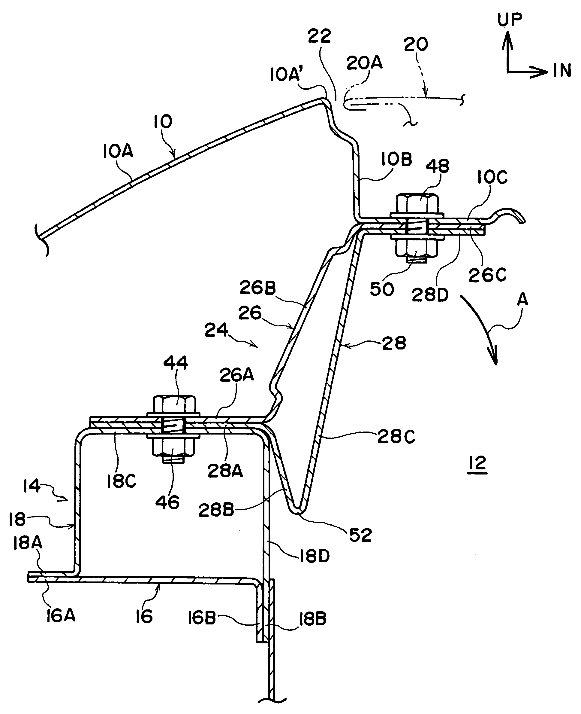
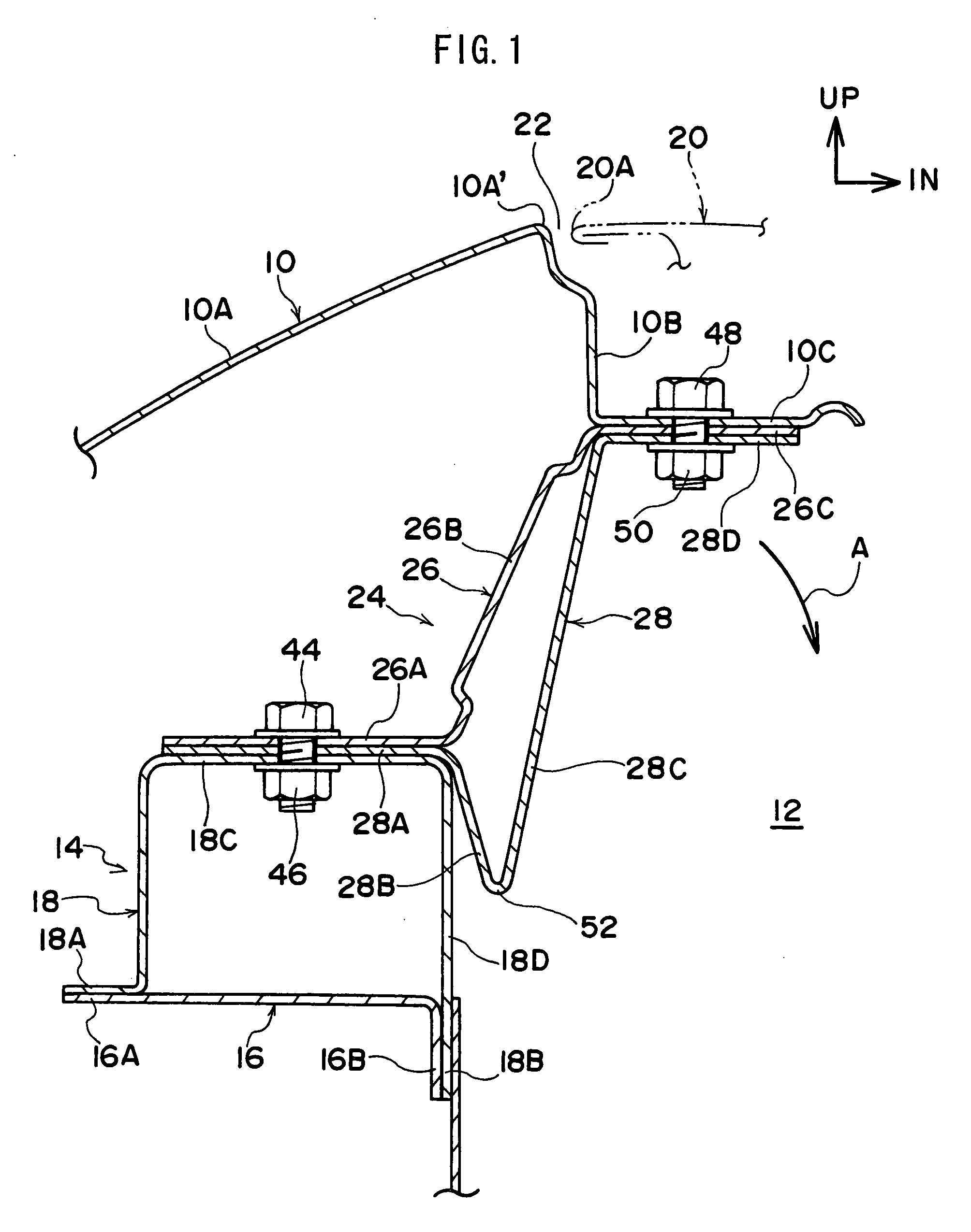
[0027]Explanation will now be given of a first exemplary embodiment of a vehicle fender panel mounting structure according to the invention, with reference to FIG. 1 to FIG. 5. It should be noted that in the figures: the arrow direction FR refers to the vehicle front direction; the arrow direction UP to the vehicle up direction; and the arrow direction IN to the vehicle width direction inside.

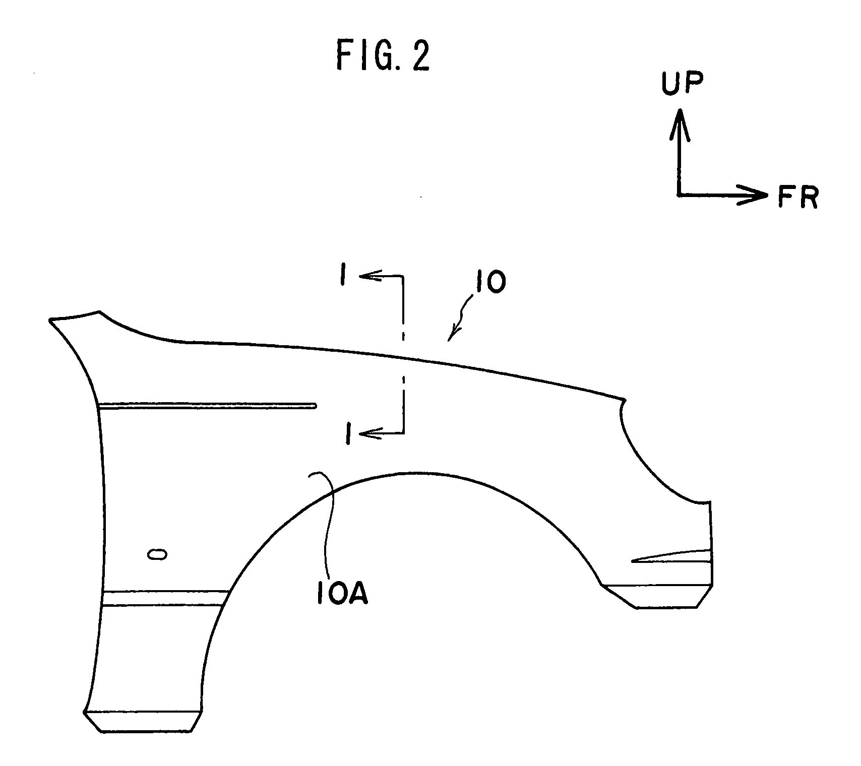
[0028]In FIG. 1, an application of the impact absorption bracket according to the present exemplary embodiment is shown in which the fender panel is in a mounted state to an apron upper member. It should be noted that FIG. 1 is a vertical cross-section showing an assembled state of the front fender panel shown in FIG. 2, sectioned along the line 1-1 and viewed from the vehicle front direction side.

[0029]As is shown in the figures, there is a front fender panel 10 provided to a side face of a vehicle front portion. The front fender panel 10 is configured including: an outside upright wall portio...

second exemplary embodiment

[0053]Explanation will now be given of a second exemplary embodiment of a vehicle fender panel mounting structure according to the present invention, with reference to FIG. 6 to FIG. 8. It should be noted that components of the configuration that are similar to those of the above described first exemplary embodiment are allocated the same reference numerals, and explanation thereof is omitted.

[0054]As shown in FIGS. 6 and 7, the vehicle fender panel mounting structure according to this second exemplary embodiment is an impact absorption bracket 60, characterized by a substantially Z-shape when viewed from the side of the vehicle front.

[0055]Specifically, the impact absorption bracket 60 is configured with a top side bracket 62 configuring the top face side thereof, and a bottom side bracket 64 configuring the bottom face side thereof. The top side bracket 62, in the same manner as that of the top side bracket 26 explained in the above described first exemplary embodiment, is configu...

third exemplary embodiment

[0067]Explanation will now be given of a third exemplary embodiment of a vehicle fender panel mounting structure according to the present invention, with reference to FIG. 9 to FIG. 11. It should be noted that components of the configuration that are similar to those of the above described first exemplary embodiment are allocated the same reference numerals, and explanation thereof is omitted.

[0068]The impact absorption brackets 70, 72, 74 explained below are characterized in that an upper portion 76 that corresponds to the top side bracket 26, and a lower portion 78 that corresponds to the bottom side bracket 28, are formed into one integral component. It should be noted that each portion of the upper portion 76 and the lower portion 78 that is common from a configuration perspective to those of the impact absorption bracket 24 explained in the first exemplary embodiment are allocated the similar reference label in which the tens digit numeral 2 is replaced with 7. For example, lab...


PUM


Abstract

A vehicle fender panel mounting structure is provided in which good protection capability may be obtained for pedestrians, even when the break line portion between the hood and the fender panel is disposed offset in the vehicle width direction further inside than the vehicle body side structural member that is the corresponding mount for the fender panel. In a body in which a break line portion, of the front fender panel and a hood, is disposed offset further to the inside in the vehicle width direction than an apron upper member, an impact absorption bracket, made up from an upper bracket and a lower bracket, is disposed in a cantilever supported state, and by rotational deformation in a direction, an outside second angled portion contacts an upright wall portion, and after that time, bending deformation occurs in a successive manner, originating at a bent portion, from an inside second angled portion toward an outside second angled portion. A reaction force in the latter half of F-S characteristics may thereby be obtained.

Description

CROSS-REFERENCE TO RELATED APPLICATION[0001]This application claims priority under 35 U.S.C 119 from Japanese Patent Application No. 2006-290059, the disclosure of which is incorporated by reference herein.BACKGROUND OF THE INVENTION[0002]1. Technical Field[0003]The present invention relates to a vehicle fender panel mounting structure.[0004]2. Related Art[0005]In Japanese Patent Application Laid-Open (JP-A) No. 2004-50865 there is described a technology of mounting, through a fender bracket that has been formed in a substantially Z-shape when viewed from the side of the vehicle front direction, a top end inside portion of a fender panel to a top end horizontal portion of an apron upper member, and furthermore of mounting a reinforcement member, formed in a stepped shape when viewed from the side of the vehicle front direction, to the fender bracket inside in the vehicle width direction.[0006]According to the above configuration, when an impact object has impacted in the vicinity of...

Claims


Application Information

Patent Timeline
IPC IPC(8): B60R19/26B60R99/00B60R21/34B62D25/08B62D25/16
CPCB62D25/163B60R2021/343B60R21/34B62D25/02B62D25/082
Inventor MITSUYAMA, SOSHI
Owner TOYOTA JIDOSHA KK
Why Eureka
Try Eureka