Apparatus and method for controlling a transfer switch mechanism

a technology of automatic transfer switch and apparatus, which is applied in the direction of dynamo-electric converter control, motor/generator/converter stopper, instrument, etc., can solve the problems of motor damage, gearbox damage, system failure to operate, etc., and achieve the effect of removing high-frequency nois

Active Publication Date: 2008-05-01
SQUARE D CO
View PDF8 Cites 31 Cited by
  • Summary
  • Abstract
  • Description
  • Claims
  • Application Information

AI Technical Summary

Benefits of technology

[0036]The monitoring can further include removing high-frequency noise from the instantaneous current. The first predetermined period can be reached when a timer has run for a predetermined amount of time. The load can be a transfer switch mechanism in an electrical distribution panel. Or, the load can be a circuit breaker.

Problems solved by technology

If the motor is continues to turn, the motor and gearbox can be damaged and cause the system to fail to operate.
The motor can be damaged by twisting the motor shaft or loosening or breaking the motor's mounting to the device.
The gearbox can be damaged by cracking the gears, breaking off gear teeth, or loosening or breaking the gearbox's mounting to the device.
Limit switches, however, suffer from low reliability, they add complexity and cost to the system, and they undesirably increase the overall size of the transfer switch.
Like the limit switches, external sensors add complexity, cost, and size to the system.
However, the actuating mechanism of a switch, such as a handle, cannot always be guaranteed to close or open the electrical contacts of the switch.
In the case of the transfer switch, such breakage would cause the mechanical interlock to fail allowing multiple sources to be connected to the load, causing two asynchronous power sources to short together thereby potentially damaging both.
A breakage could also cause a powered source to reverse power an un-powered source.
If a backup generator were running and connected to an un-powered utility line, the utility line would become back-fed and pose a serious safety hazard to the utility lineman.

Method used


Image

  • Apparatus and method for controlling a transfer switch mechanism
  • Apparatus and method for controlling a transfer switch mechanism
  • Apparatus and method for controlling a transfer switch mechanism

Examples


Embodiment Construction

[0071]Although the invention will be described in connection with certain preferred embodiments, it will be understood that the invention is not limited to those particular embodiments. On the contrary, the invention is intended to include all alternatives, modifications and equivalent arrangements as may be included within the spirit and scope of the invention as defined by the appended claims.

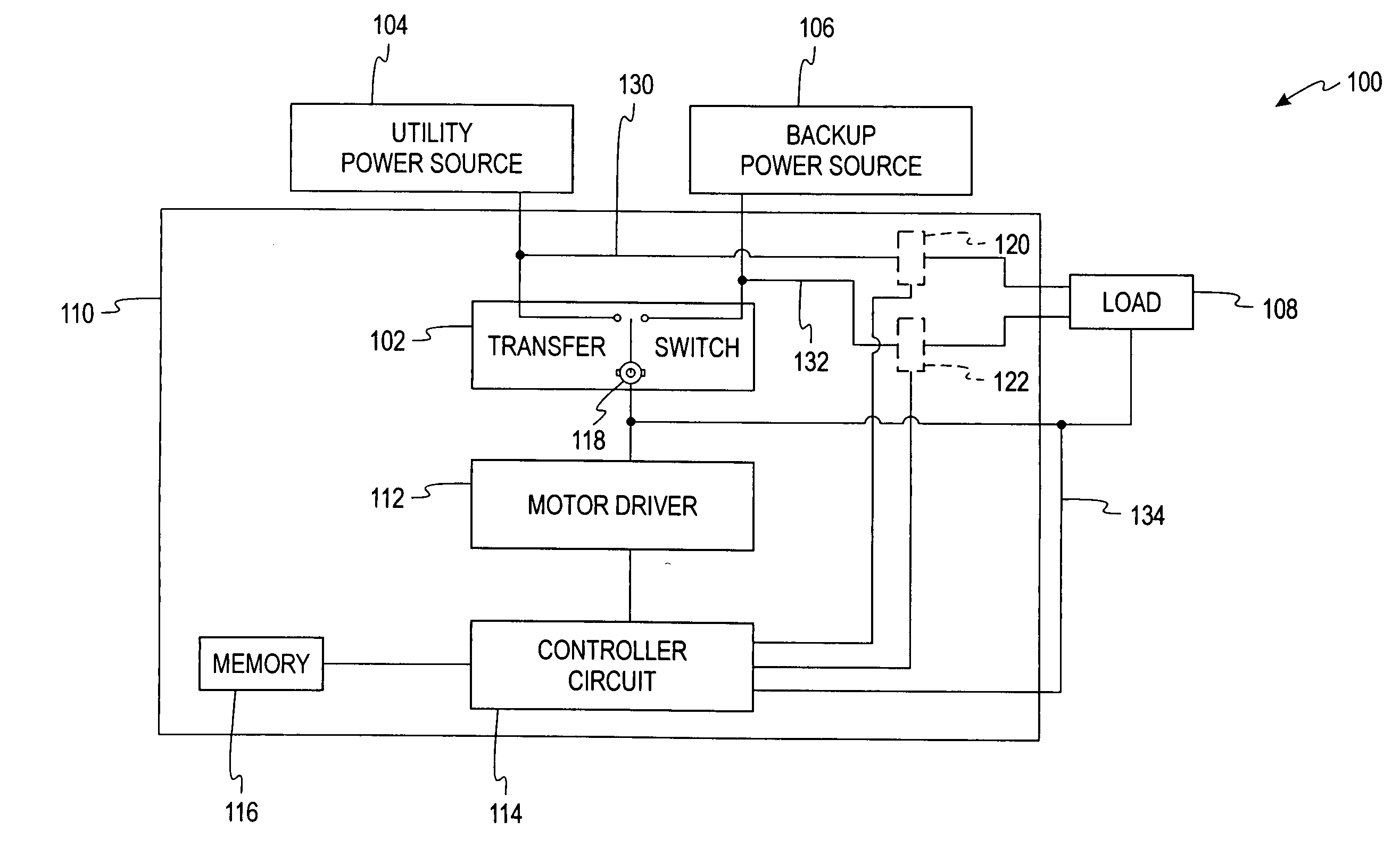
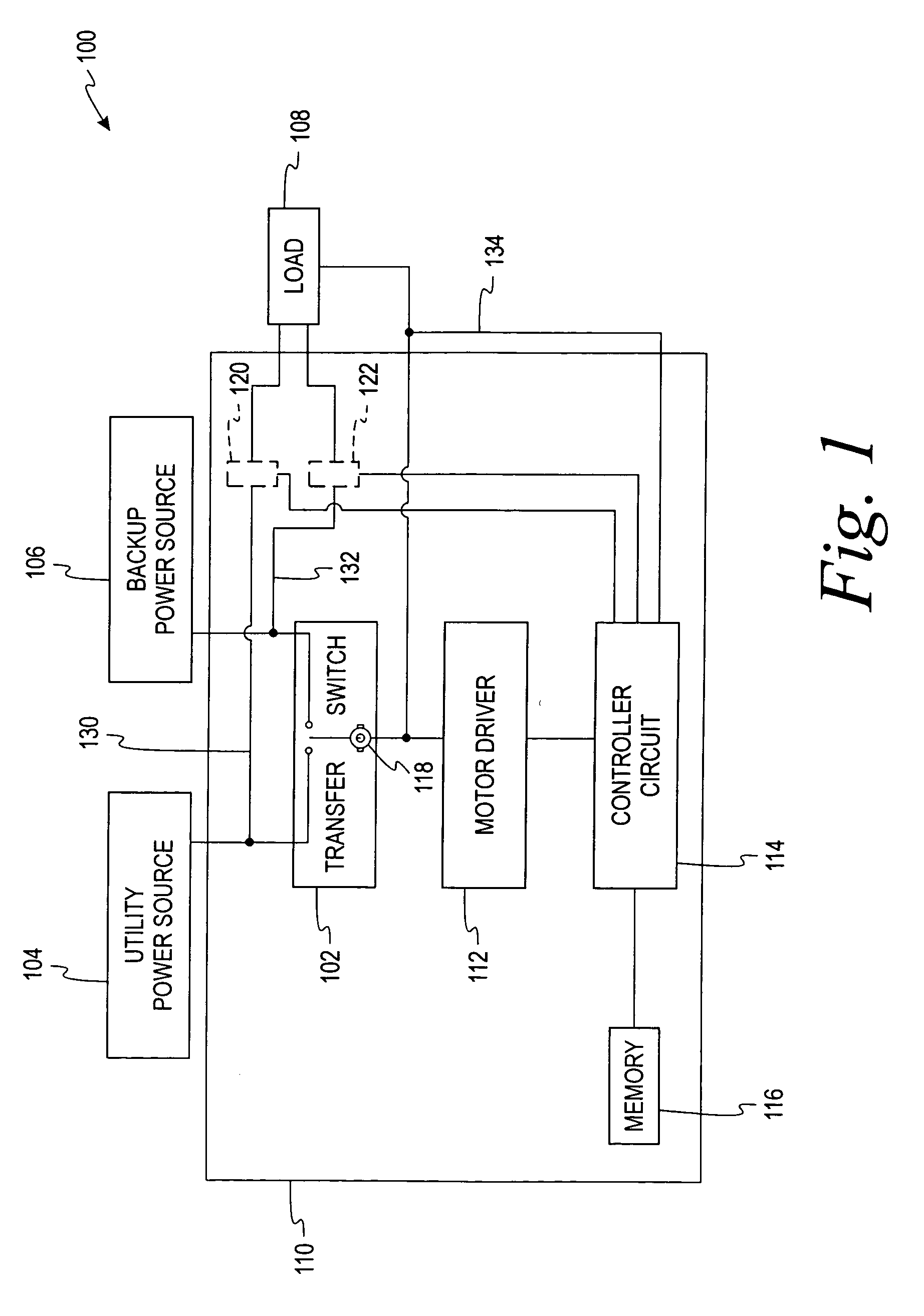
[0072]Referring now to the drawings and initially to FIG. 1, a functional block diagram of a system 100 for controlling an automatic transfer switch mechanism 102 according to an aspect of the present invention. The transfer switch mechanism 102 allows electrical power to flow from a utility (main) power source 104 or a backup power source 106 (such as a generator) to a load 108. An automatic transfer switch mechanism with a manual override suitable for use with aspects of the present invention is disclosed in U.S. Patent Application Publication No. 2006 / 0131146, entitled “Switching Mechanism...


PUM


Abstract

A controller for an automatic transfer switch mechanism in an electrical distribution panel, which automatically determines motor phase by monitoring the back EMF voltage of the motor when no power is applied to the motor as defined by a pulse width modulation circuit. Phase comparisons of the voltage on the line and load sides of the transfer switch mechanism determine the position of the transfer switch mechanism.

Description

FIELD OF THE INVENTION[0001]This invention is directed generally to transfer switch mechanisms, and, more particularly, to an apparatus and method for automatically controlling an automatic transfer switch mechanism.BACKGROUND OF THE INVENTION[0002]A transfer switch is an electromagnetic mechanism that controls to which power source a load is connected, such as between a utility (main) power source and a backup power source. An automatic transfer switch can include a DC motor that drives an attached mechanical device, which is typically coupled to the motor through an intermediary gearing system such as a gearbox.[0003]As the motor is switching between power sources, eventually the mechanism will reach a point where it cannot be moved any further, requiring intervention to stop the motor from driving the mechanism. If the motor is continues to turn, the motor and gearbox can be damaged and cause the system to fail to operate. The motor can be damaged by twisting the motor shaft or l...

Claims


Application Information

Patent Timeline
Patent Type & Authority Applications(United States)
IPC IPC(8): H02P7/00
CPCH01H2300/018H02J9/061H02P6/182H02J2009/068H02J9/066H02J9/068
Inventor FILIPPENKO, ALEXANDER S.
Owner SQUARE D CO
Why Eureka
Try Eureka