
Ethernet OAM at intermediate nodes in a PBT network

Inactive Publication Date: 2008-05-01
RPX CLEARINGHOUSE
View PDF6 Cites 55 Cited by
  • Summary
  • Abstract
  • Description
  • Claims
  • Application Information

AI Technical Summary

Benefits of technology

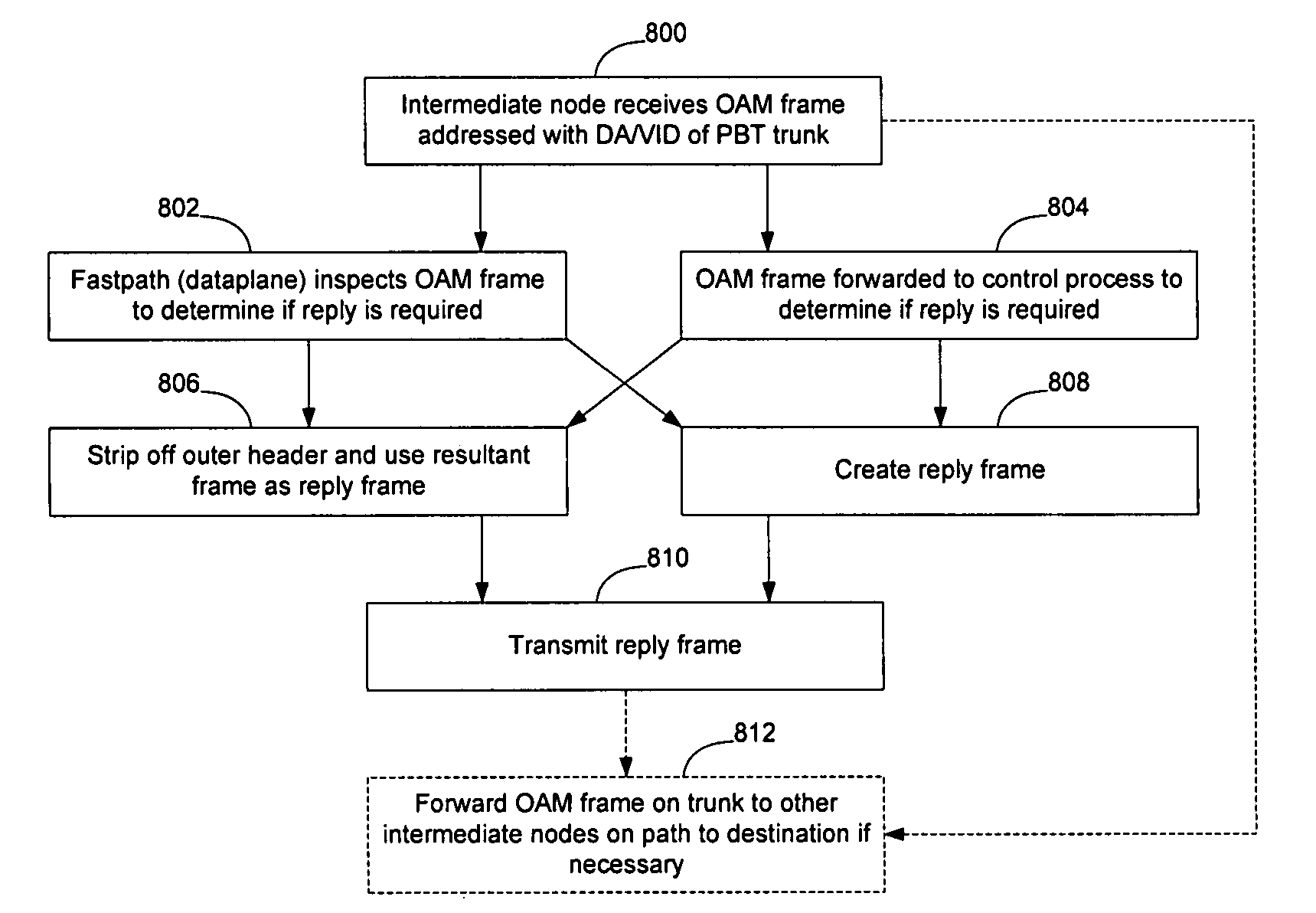
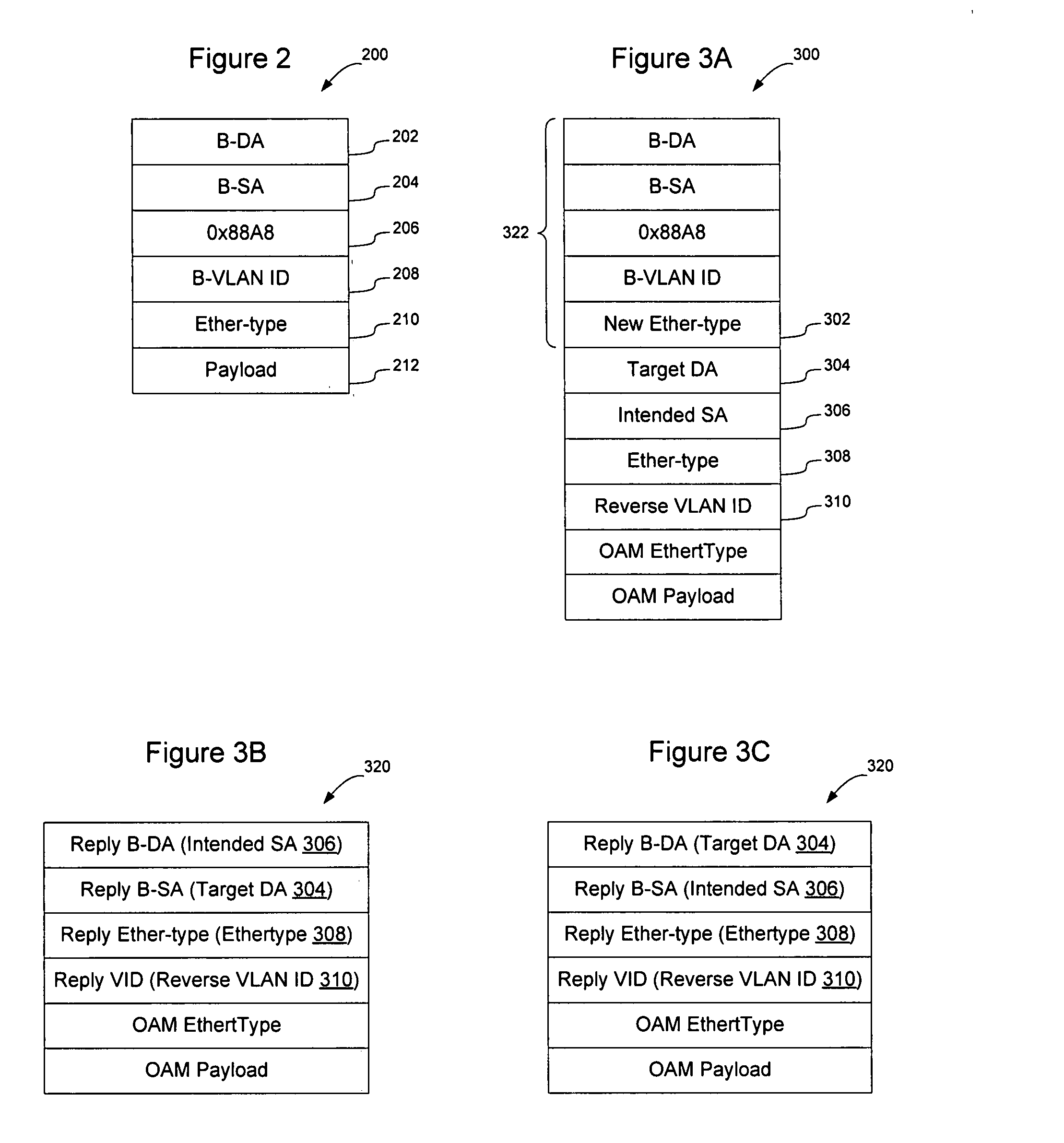
[0018]To prevent the intermediate nodes from being required to maintain a correlation between forward and reverse trunks, the OAM frame may be configured to contain reply address information such as the DA / VID of the reverse trunk so that reply messages generated in response to the OAM frame may be passed over the reverse trunk.

Problems solved by technology

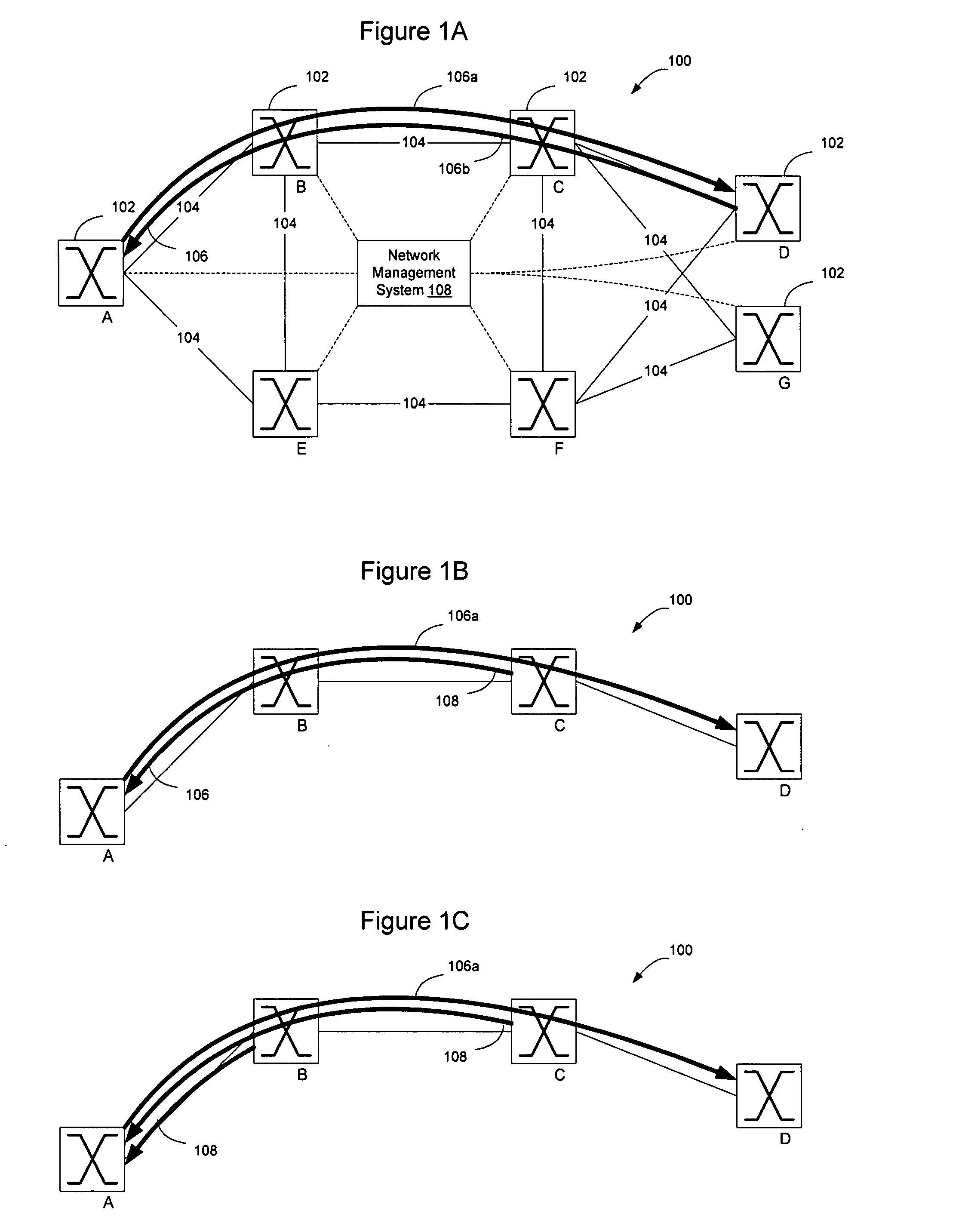
Depending on the manner in which PBT is implemented, the forward and reverse trunks may be independent of each other, such that intermediate nodes on the trunks may not maintain a correlation of forwarding information for trunks extending in opposite directions between pairs of sources and destinations on the network.
Accordingly, network element C may never receive the OAM frame and wouldn't therefore be able to respond to it.
The combination of a possible lack of correlation between forwarding and reverse path, and the fact that frames that are addressed to intermediate nodes will be dropped by other intermediate nodes on a the network complicates intermediate node OAM in a PBT network.
Finally, even if the intermediate node does recognize the OAM message and process the OAM message, it will not know how to reply to the OAM message since it will not have the VID that is used by the trunk in the reverse direction.
Thus, the intermediate node may not be able to create a frame that will be handled by the other intermediate nodes as an ordinary frame on the reverse trunk.
Thus, even if the OAM message is received and processed by an intermediate node, the intermediate node may not be able to create a reply frame that is able to be transmitted over the reverse trunk 106b.

Method used


Image

  • Ethernet OAM at intermediate nodes in a PBT network
  • Ethernet OAM at intermediate nodes in a PBT network
  • Ethernet OAM at intermediate nodes in a PBT network

Examples


Embodiment Construction

[0034]The following detailed description sets forth numerous specific details to provide a thorough understanding of the invention. However, those skilled in the art will appreciate that the invention may be practiced without these specific details. In other instances, well-known methods, procedures, components, protocols, algorithms, and circuits have not been described in detail so as not to obscure the invention.

[0035]FIG. 1 shows a portion of an example Ethernet network 100 in which network elements 102 are interconnected by links 104. PBT trunks 106a, 106b may be established through the Ethernet network 100 as described in greater detail in U.S. patent application Ser. No. 10 / 818,685, entitled Traffic Engineering in Frame-Based Carrier Networks”, the content of which is hereby incorporated herein by reference.

[0036]PBT trunks 106 are created to extend one way though the Ethernet network 100 by causing forwarding state to be installed on intermediate nodes that will cause the in...


PUM


Abstract

OAM may be implemented at an intermediate node on a PBT trunk in an Ethernet network by causing OAM frames to be addressed to the PBT trunk endpoint but causing the OAM frames to carry an indicia (Ether-type, OpCode, TLV value or combination of these and other fields) that the OAM frames are intended to be used for intermediate node OAM functions. The Ether-type, OpCode, and TLV values may be standardized values, or vendor specific values such as OpCode=51 or TLV=31 may be used. Addressing the OAM frames to the PBT trunk end point enables the OAM frames to follow the PBT trunk through the network. The OAM indicia signals to the intermediate nodes that the OAM frames are intended to be used to perform an intermediate node OAM function. The OAM frames may contain reverse trunk information to prevent the intermediate nodes from being required to store correlation between forward and reverse PBT trunks.

Description

CROSS REFERENCE TO RELATED APPLICATIONS [0001]This application is related to and claims the benefit of U.S. Provisional Application No. 60 / 855,550, filed Oct. 31, 2006, entitled “OAM For Differential Forwarding in Address Based Networks,” the content of which is hereby incorporated herein by reference.BACKGROUND OF THE INVENTION [0002]1. Field of the Invention[0003]The present invention relates to communication networks and, more particularly, to a method and apparatus for implementing Ethernet OAM at intermediate nodes in a Provider Bridged Transport (PBT) network.[0004]2. Description of the Related Art[0005]Data communication networks may include various routers, switches, bridges, hubs, and other network devices coupled to and configured to pass data to one another. These devices will be referred to herein as “network elements.” Data is communicated through the data communication network by passing protocol data units, such as Internet Protocol (IP) packets, Ethernet Frames, data...

Claims


Application Information

Patent Timeline
IPC IPC(8): H04L12/26H04L69/40
CPCH04L41/0213H04L12/4641
Inventor MOHAN, DINESHMONTI, CHRISTOPHERROMANUS, PIOTRTSANG, DAVIDCHEN, MICHAEL
Owner RPX CLEARINGHOUSE
Learn More