Heat exchanger

a technology of heat exchanger and ion exchanger, which is applied in the direction of lighting, heating apparatus, and semiconductor/solid-state device details, etc., can solve the problems of large cooling device size, local temperature rise, and high voltage risk of cooling device using corona discharge, so as to reduce the distance between electrodes and the number of discharge sections , the effect of stabilizing the ionic wind

Inactive Publication Date: 2010-12-09
SHARP KK
View PDF59 Cites 26 Cited by
  • Summary
  • Abstract
  • Description
  • Claims
  • Application Information

AI Technical Summary

Benefits of technology

[0020]The heat exchanger of the present invention includes the electron emitting element provided so as to be separated from the electrically conductive contact member which is in contact with the target of heat exchange. Further, the electron emitting element includes: the electrode substrate; the thin-film electrode; the first voltage applying means for applying the voltage between the electrode substrate and the thin-film electrode; and the electron acceleration layer which accelerates the electron inside itself in response to the voltage from the first voltage applying means so that the electron is emitted from the thin-film electrode. In addition, the electron acceleration layer is formed at least partially with an insulating material. This arrangement allows for provision of the electron emitting element which can emit electrons in an internal electric field. In other words, the electron emitting element provides electrons to the contact member via the air present in the space between the electron emitting element and the contact member. These electrons collide with air molecules present in the space. This collision ionizes the air molecules. Further, these ionized air molecules move along an electric field, and thus generate an ionic wind. The ions then arrive at the contact member. This stirs air molecules which are present along the surface of the heat source.
[0021]As described above, according to the above arrangement, the electron emitting element which can emit electrons in an internal electric field is provided, instead of a conventional wire electric discharge element, so as to be separated from the contact member. As a result of this, even with a structure in which electric field concentration tends to occur in the vicinity of the contact member, the electron emitting element can stably provide electrons into the atmosphere, and thus generate an ionic wind. In addition, it is possible to stably provide an ionic wind even if the contact member has a complex shape. In other words, the heat exchanger of the present invention generates an ionic wind not with use of a conventional wire electric discharge element which causes a corona discharge, but with use of the electron emitting element which can emit electrons in an internal electric field. Thus, it is not necessary to reduce the number of discharge sections for device downsizing, unlike in conventional ionic-wind cooling devices. Furthermore, it is not necessary to reduce the distance between electrodes for wire electric discharge. Thus, the above arrangement prevents problems associated with conventional ionic-wind cooling devices which cause a corona discharge, the problems including a problem concerned with a distance between electrodes for wire electric discharge. In a case where, for example, the contact member is a heat sink, the above arrangement, in view of device downsizing, allows a device having a certain size to include more fins than a conventional ionic wind generator. This consequently improves a heat exchange capability.
[0022]As described above, the above arrangement allows for provision of the heat exchanger having a heat exchange capability which can be maintained and improved independently of a structure in which electric field concentration tends to occur.

Problems solved by technology

However, the wire electric discharge (corona discharge) performed by the ionic-wind cooling device disclosed in Patent Literature 3 poses a problem described below.
Thus, a cooling device using a corona discharge involves a risk of a high voltage.
In addition, the large interelectrode distance problematically results in a large-size cooling device.
This results in a local temperature rise.
This temperature rise then leads to breaking of a wire electrode and / or damage to a heat source.
This problematically prevents maintenance and improvement of a cooling capability of the cooling device.

Method used


Image

  • Heat exchanger
  • Heat exchanger
  • Heat exchanger

Examples


embodiment 1

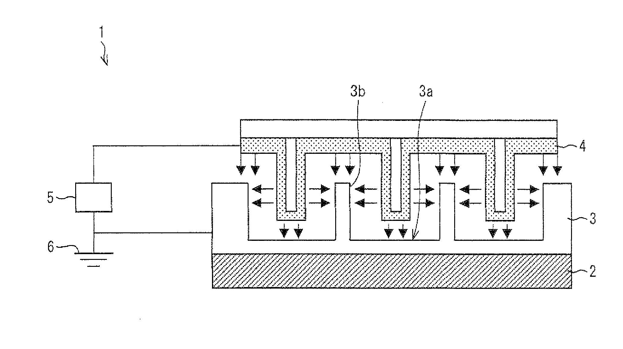
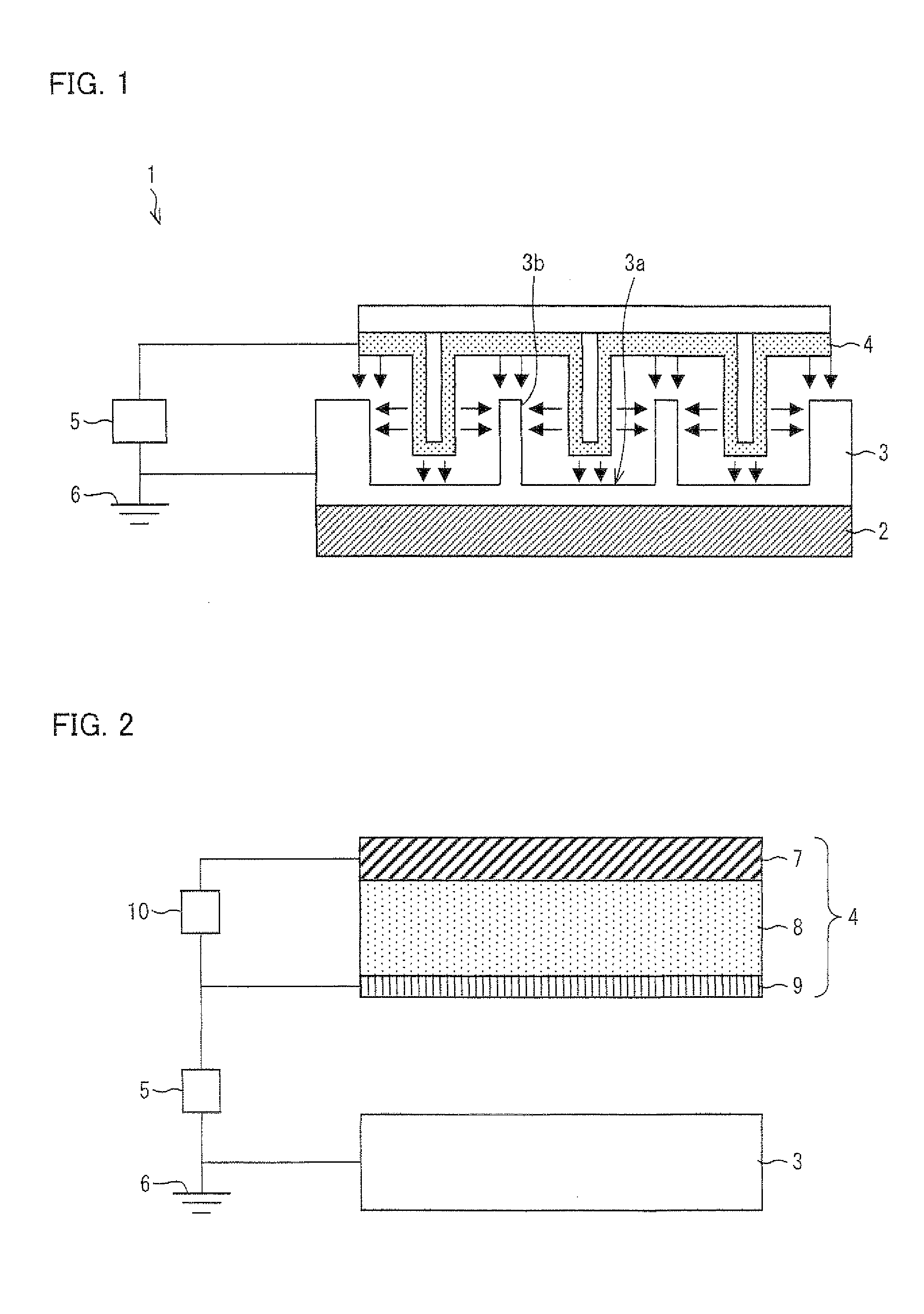
[0058]One embodiment of the present invention is described below with reference to FIGS. 1 through 9. Note that an arrangement described below is merely a specific example of the present invention. Thus, the present invention is not limited to this arrangement. FIG. 1 is a cross-sectional view illustrating a preferable example of a heat exchanger (cooling device) 1 according to the present embodiment.

[0059]The heat exchanger 1 is a device for releasing, to the outside, heat generated by a heating element (target of heat exchange) 2. The heat exchanger 1 includes: a heat sink (contact member) 3; an electron emitting element 4; and a power supply (second voltage applying means) 5. The heat sink 3, which is made of a conductive material, is in contact with the heating element 2. The heat sink 3 has a surface 3a opposite from the heating element 2 which surface is in contact with air. The heat sink 3 includes a plurality of convexities 3b formed at least partially along the surface. The...

example 1

[0079]With reference to FIGS. 5 and 6, the following describes, as an example, experiments for verifying the heat dissipation effect achieved by the heat exchanger according to the present invention. Note that these experiments merely serve as example embodiments, and that the description of the experiments does not limit the scope of the present invention.

[0080]The experiments of the present example were conducted with use of a heat exchanger illustrated in FIG. 5. The heat exchanger illustrated in FIG. 5 was equipped with a fan 14 (airflow generator) so that the fan would blow air toward the heat sink 3. The heating element 2 serving as the heat source was arranged to start or stop generating heat in response to an on-off action of a switch. When the switch was turned off, the heating element would stop generating heat. In the present example, the heat generation by the heating element 2 was stopped (i.e., the switch was turned off) simultaneously with a start of temperature measu...

embodiment 2

[0085]Another embodiment of the present invention is described below with reference to FIG. 7.

[0086]A heat exchanger of the present embodiment has an arrangement and a drive principle which are basically identical to those of the heat exchanger according to Embodiment 1. Such identical parts of the arrangement and the drive principle are not described here. The heat exchanger of the present embodiment differs from the heat exchanger of Embodiment 1 in how the electron emitting element is arranged. FIG. 7 is a view illustrating the arrangement of the electron emitting element and its surroundings of the heat exchanger according to the present embodiment.

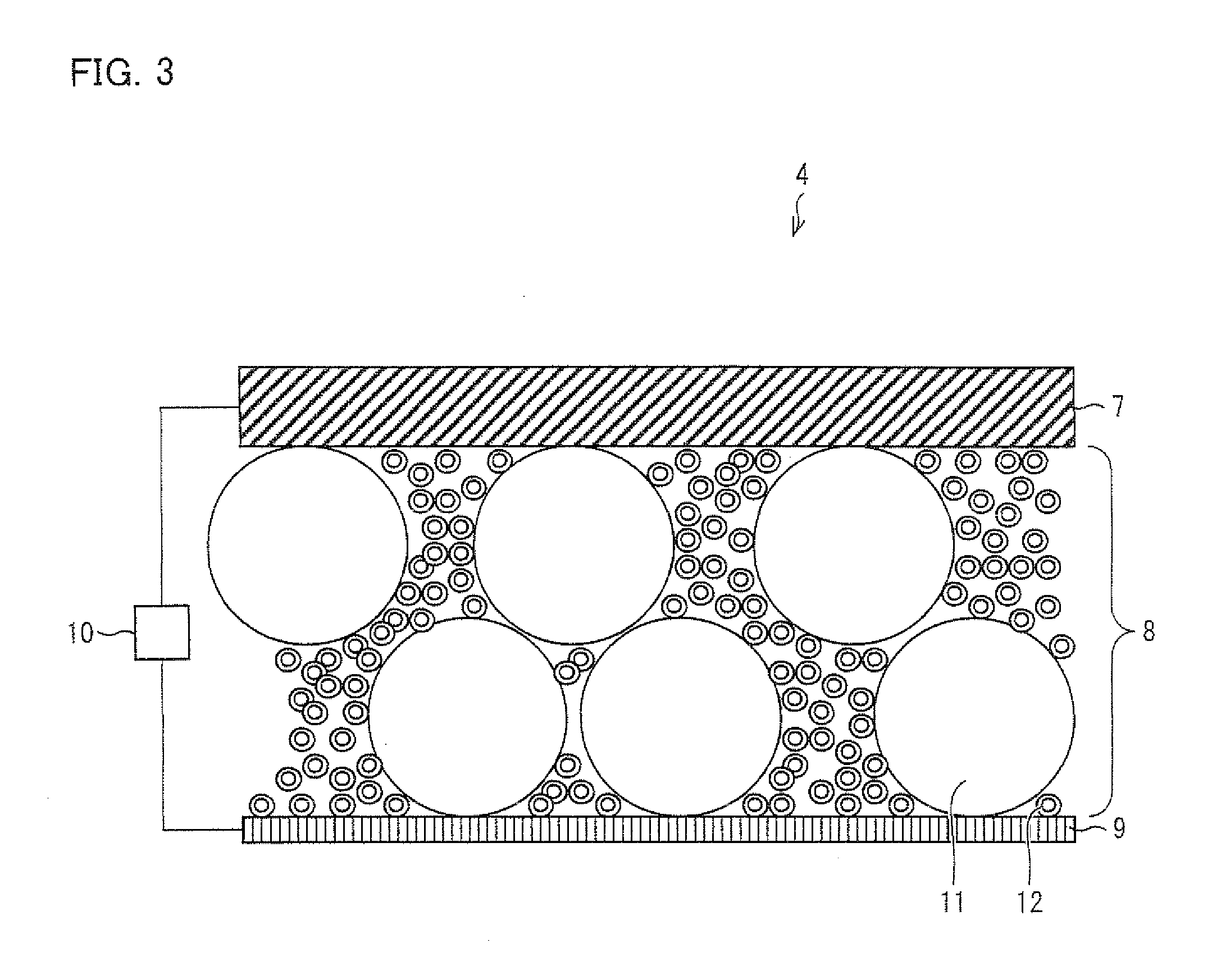
[0087]As illustrated in FIG. 7, the electron emitting element 16 is characterized by its flexibility. The electron emitting element 16 includes: a flexible substrate 18; a substrate thin-film electrode 17; the electron acceleration layer 8; and the thin-film electrode 9. The substrate thin-film electrode 17 and the thin-film electrode...


PUM

PropertyMeasurementUnit
diameteraaaaaaaaaa
diameteraaaaaaaaaa
thicknessaaaaaaaaaa

Abstract

A heat exchanger (1) includes: a heat sink (3) which is in contact with a heating element (2); and an electron emitting element (4) which is provided so as to be separated from the heat sink (3) by a space and which provides electrons to the heat sink (3) via air in the space. The electron emitting element (4) includes: an electrode substrate (7); a thin-film electrode (9); a power supply (10) which applies a voltage between the electrode substrate (7) and the thin-film electrode (8); and an electron acceleration layer (8) which accelerates the electrons inside itself in response to the voltage applied by the power supply (10) so that the electrons are emitted from the thin-film electrode (9). The electron acceleration layer (8) is made at least partially of an insulating material. As a result, the heat exchanger (1) has a heat exchange capability which can be maintained and improved independently of a structure in which electric field concentration tends to occur.

Description

TECHNICAL FIELD[0001]The present invention relates to a heat exchanger.BACKGROUND ART[0002]Conventionally, a rotary-blade airflow generator (hereinafter referred to as “fan”) has normally been used as a means of cooling a heating element. However, the use of a fan for such cooling causes a problem of large noise made by the fan in operation. To solve this problem, cooling with use of an ionic wind caused by a corona discharge has been devised to replace the cooling with the use of a fan (see, for example, Patent Literatures 1 and 2). The use of an ionic wind eliminates wind noise peculiar to operation of a fan, and thus reduces noise. Further, the following is known (see Non Patent Literature 1): A heat source (heating element) is cooled more effectively when air blown by a fan is used in combination with an ionic wind than when air blown by a fan is solely used. Non Patent Literature 2 describes a condition necessary for a corona discharge to be stably generated.[0003]The following...

Claims


Application Information

Patent Timeline
Patent Type & Authority Applications(United States)
IPC IPC(8): F28F13/00F28F13/18
CPCF28F13/16G06F1/20G06F1/203H01L23/467H05K7/20172H01L2924/0002H05K7/20972H01L2924/00
Inventor ICHII, YOSHIOIWAMATSU, TADASHIHIRAKAWA, HIROYUKIKANDA, HIROFUMI
Owner SHARP KK
Why Eureka
Try Eureka