Fiber optic protective shutter

a protective cap and fiber technology, applied in the field of optical fibers, can solve the problems of affecting the optical transmission ability of the fiber, affecting the safety of operators, so as to improve the ease of disassembly and disassembly of the protective cap from the coupler

Inactive Publication Date: 2008-05-01
SENKO ADVANCED COMPONENTS
View PDF9 Cites 113 Cited by
  • Summary
  • Abstract
  • Description
  • Claims
  • Application Information

AI Technical Summary

Benefits of technology

[0005] Various aspects of the invention may provide one or more of the following capabilities. A protective shutter for a fiber optic connector that attenuates electromagnetic radiation and prevents dust and other contaminants from entering the connector may be provided. Foreign matter is substantially prevented from entering the housing. Guiding slots in the walls of the connector increase the ease with which the protective cover and the fiber coupler are connected. Ease of disassembly of the protective cap from a coupler is improved.

Problems solved by technology

Often, fiber ends may be damaged by adverse environmental hazards, particularly at the location where optical fibers terminate in connectors.
In particular, dust, dirt, and debris may impair the optical transmission capabilities of the fiber.
Also, since a laser beam passes through the fiber, an operator's eyes may easily be injured while the connector is not in use or is not covered.

Method used


Image

  • Fiber optic protective shutter
  • Fiber optic protective shutter
  • Fiber optic protective shutter

Examples


Embodiment Construction

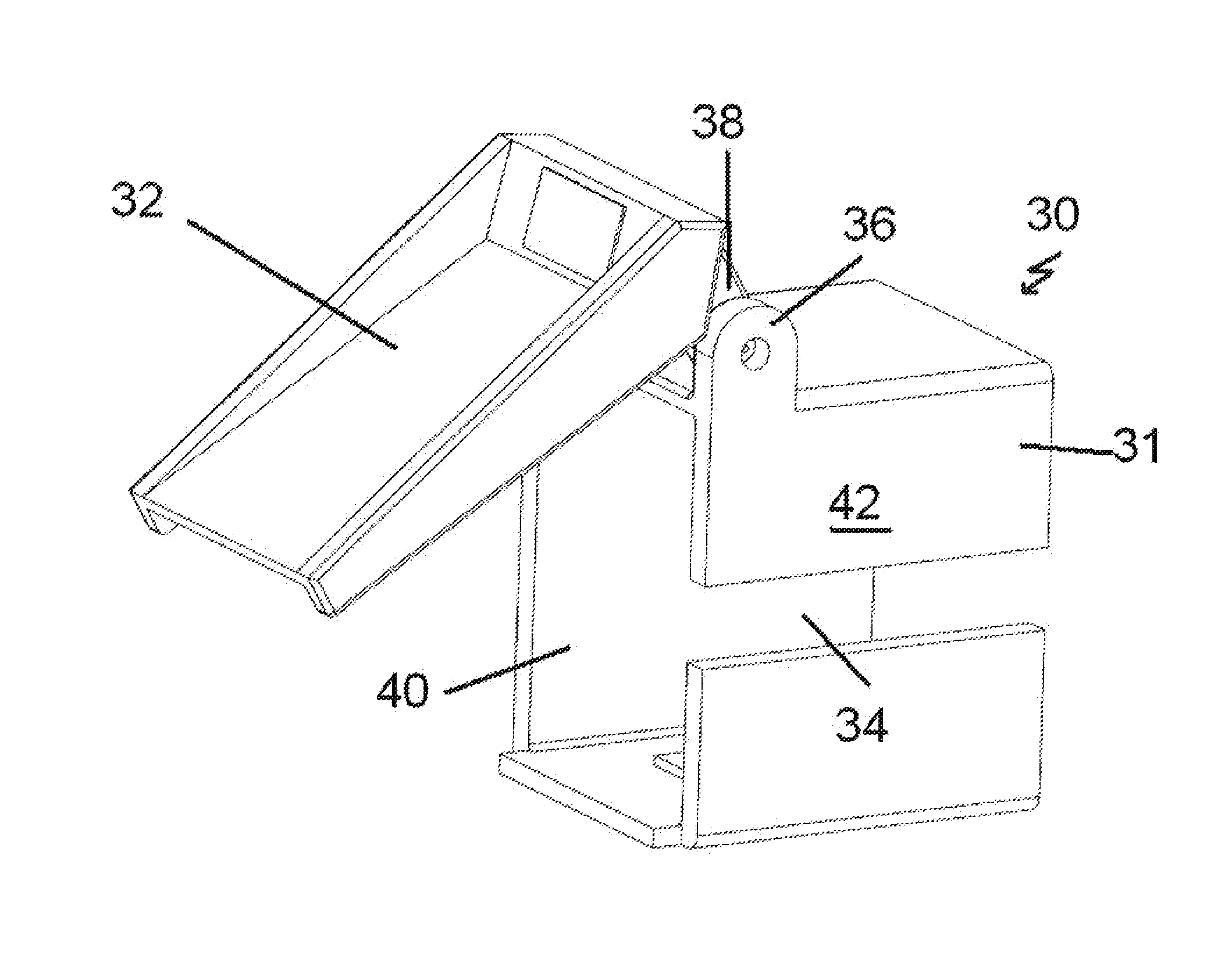
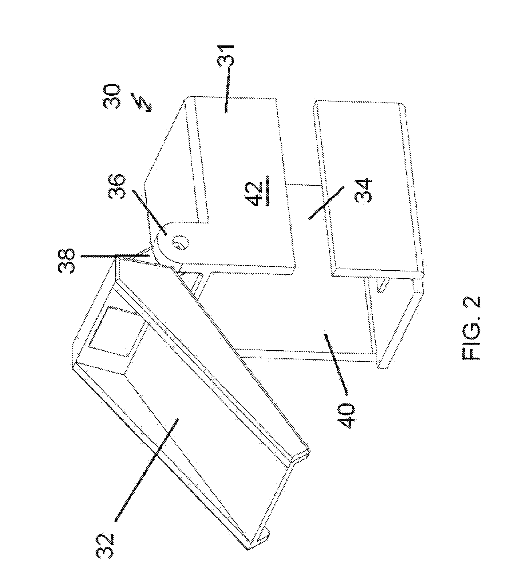
[0012] Embodiments of the invention provide products and techniques for protecting a fiber optic coupler from contamination by dust, debris or other environmental hazards. Exemplary embodiments of the invention include a protective cap and a protective shutter. The protective cap includes an open slot in the side that aligns with a guiding slot in the fiber coupler. The movable shutter covers the receiving recess in the protective cap and coupler, thereby preventing contamination from entering the coupler. The open slot in the side of the cap allows the user to remove the cap after it has been placed on the fiber coupler. The cap is slid off the coupler by inserting a tool in the slot and prying apart. The protective cap is configured to slide onto the fiber coupler for connection. Other embodiments are within the scope of the invention.

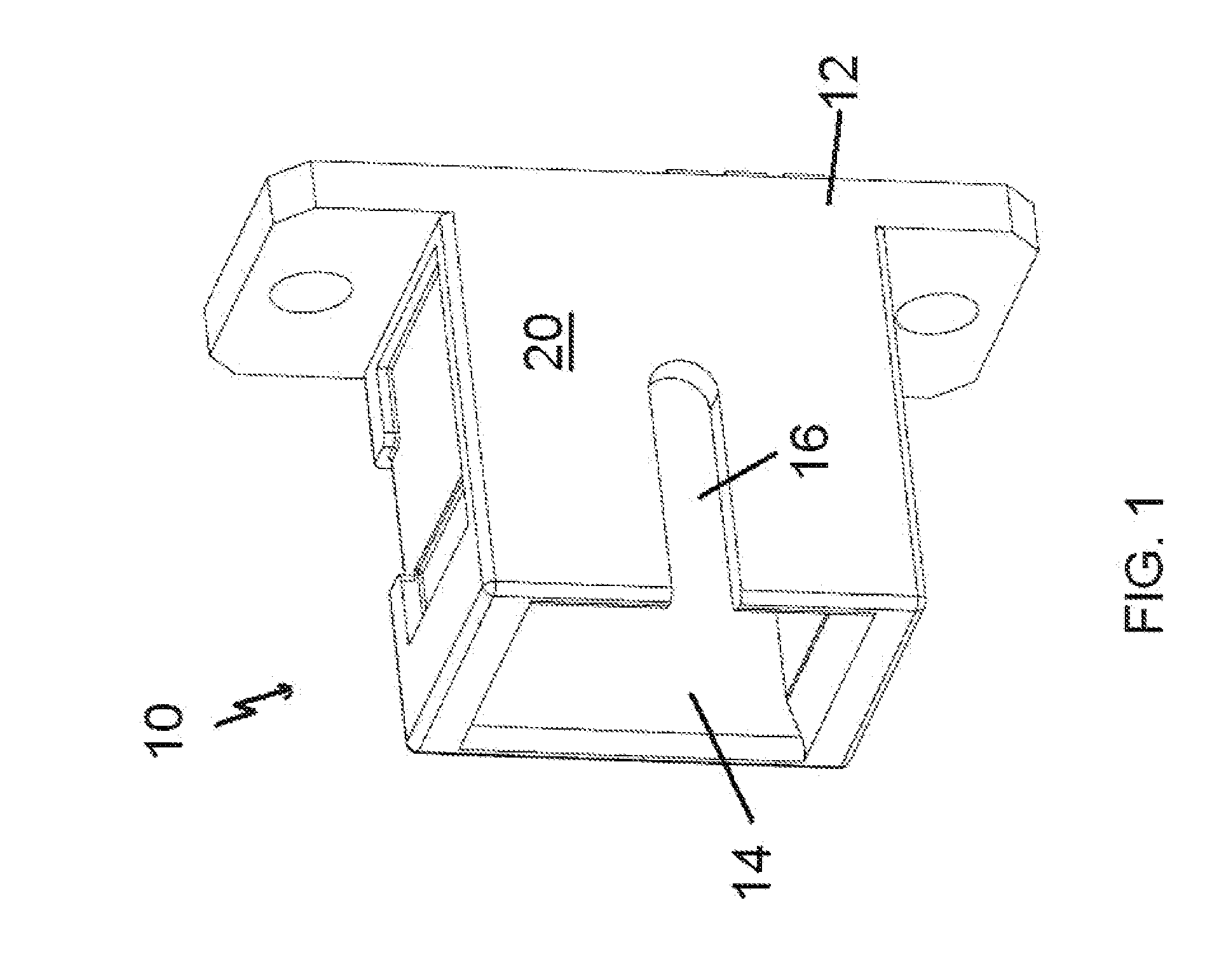
[0013] Referring to FIG. 1, a fiber optic coupler 10 includes a body 12 having a recess 14 and a guide slot 16. The recess 14 is configured to rece...


PUM


Abstract

A protection system for a fiber optic coupling having a first housing with a guide slot in a side wall includes a protective cap with a slot in a side wall and defining a passage for receiving the first housing whereby the protective cap slot aligns with the guide slot in the first housing and a protective shutter pivotally connected to the protective cap for covering a distal end of the fiber optic coupling.

Description

RELATED APPLICATIONS [0001] This application claims priority to U.S. Provisional Application No. 60 / 944,926, filed Jun. 19, 2007 and entitled, “Fiber Optic Protective Shutter,” which is herein incorporated by reference. This application is a continuation-in-part of U.S. patent application Ser. No. 11 / 508,446, filed Aug. 22, 2006 and of the same title, which application has been allowed, and which application is herein incorporated by reference.BACKGROUND OF THE INVENTION [0002] In the optical fiber field, light-guide fibers are used in optical transmission systems wherein the fibers are connected end-to-end to transfer light or optical energy. Often, fiber ends may be damaged by adverse environmental hazards, particularly at the location where optical fibers terminate in connectors. In particular, dust, dirt, and debris may impair the optical transmission capabilities of the fiber. Also, since a laser beam passes through the fiber, an operator's eyes may easily be injured while the ...

Claims


Application Information

Patent Timeline
Patent Type & Authority Applications(United States)
IPC IPC(8): G02B6/00
CPCG02B6/3849
Inventor LIN, SAMUEL I. ENO'RIORDEN, STEPHEN
Owner SENKO ADVANCED COMPONENTS
Why Eureka
Try Eureka