Relocation system and a relocation method
- Summary
- Abstract
- Description
- Claims
- Application Information
AI Technical Summary
Benefits of technology
Problems solved by technology
Method used
Image

Examples
first embodiment
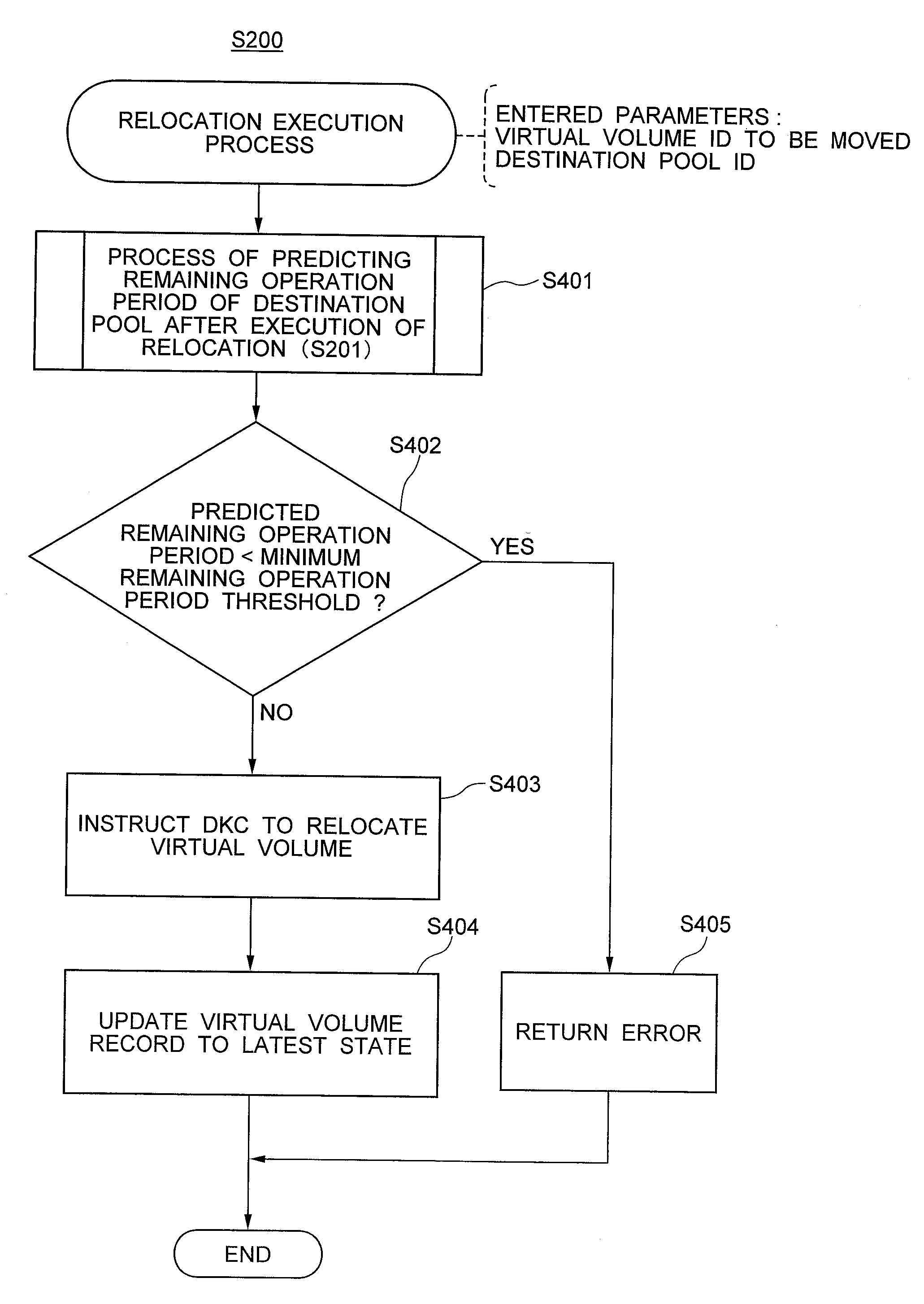
[0076]FIG. 3 shows the configuration of the relocation control section according to a first embodiment. The relocation control section 101 consists of relocation execution process S200, process of estimating the remaining operation period of a destination pool after executing relocation S201, remaining operation period estimation process S202, and usage amount prediction function update process S203. Details on the processes will be shown below.
[0077]FIG. 4 shows the structure of a database according to the first embodiment. The database 102 consists of a virtual volume table 210, a pool table 211, a virtual volume usage amount prediction function table 212, and a virtual volume usage amount history table 213.
[0078]The structures of these tables in the database 102 will be described below.
[0079]FIGS. 5A to 5D show the structures of the tables in the database shown in FIG. 4. The virtual volume table 210 is composed of collection of virtual volume records 300 that store attribute inf...
second embodiment
[0108]A second embodiment of the present invention will be described. The second embodiment is a variation of the first embodiment. A characteristic of this embodiment is that pools are classified into tiers and a virtual volume can be relocated to a designated tier in consideration of remaining operation periods of the pools.
[0109]FIG. 11 shows the configuration of the relocation control section of the second embodiment. Components common to those shown in FIG. 3 are given the same reference numerals and descriptions of them are omitted. The relocation control section 101 includes a tier-designated relocation execution process S800 and a destination pool selection process S801 as additional modules. As illustrated in FIG. 11, these additional modules are shown with their reference numerals drawn in a box for easy distinction. This applies to embodiments discussed below.
[0110]FIG. 12 shows the structure of a database according to the second embodiment. Components common to those sho...
third embodiment
[0125]A third embodiment of the present invention will be described. The third embodiment is a variation of the second embodiment. A characteristic of this embodiment is that it decides a relocation plan for relocating a virtual volume within the same tier in order to level remaining operation periods of pools in the same tier.
[0126]FIG. 17A shows the configuration of the relocation control section according to the third embodiment and FIG. 17B shows the structure of a database according to the third embodiment. Components common to those shown in FIGS. 11 and 12 are given the same reference numerals and descriptions of them are omitted. The relocation control section 101 deletes the tier-designated relocation execution process S800 (see FIG. 11) and includes a within-tier leveling process S1000 and a within-tier leveling plan selection process S1001 as additional modules. The database 102 is the same as that of the second embodiment.
[0127]FIG. 18 is a flowchart illustrating the wit...
PUM
 Abstract
Description
Claims
Application Information
 - R&D
- Intellectual Property
- Life Sciences
- Materials
- Tech Scout
- Unparalleled Data Quality
- Higher Quality Content
- 60% Fewer Hallucinations
Browse by: Latest US Patents, China's latest patents, Technical Efficacy Thesaurus, Application Domain, Technology Topic, Popular Technical Reports.
© 2025 PatSnap. All rights reserved.Legal|Privacy policy|Modern Slavery Act Transparency Statement|Sitemap|About US| Contact US: help@patsnap.com