Heat dissipation apparatus

Inactive Publication Date: 2008-05-08
HON HAI PRECISION IND CO LTD
View PDF16 Cites 47 Cited by
  • Summary
  • Abstract
  • Description
  • Claims
  • Application Information

AI Technical Summary

Problems solved by technology

However, due to the rapid development of the electronics industry, heat dissipation apparatuses with integrally formed fin assemblies can not satisfy the heat dissipation requirements of high frequency products.
This is due to the density of fins and width-height ratio of each fin of the integrally formed fin assembly being limited by the techniques used to manufacture them.
Increases in the heat dissipating area of the integrally formed fin assembly are thus limited, which also limits improvements in the heat dissipation efficiency of the heat dissipation apparatus.
However, the more complicated manufacture of the stacked fin assembly increases the cost of the improved heat dissipation apparatus.

Method used


Image

  • Heat dissipation apparatus
  • Heat dissipation apparatus
  • Heat dissipation apparatus

Examples


Embodiment Construction

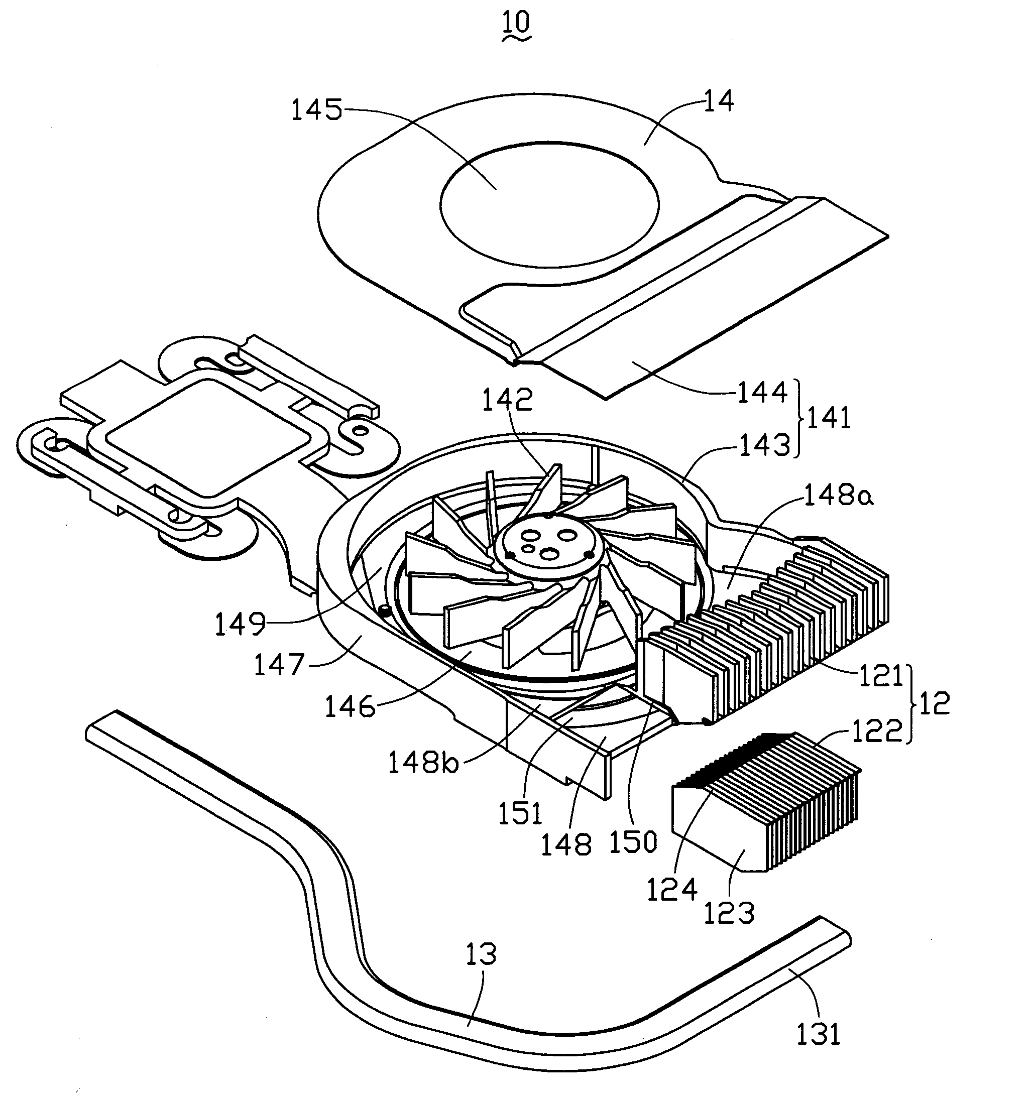
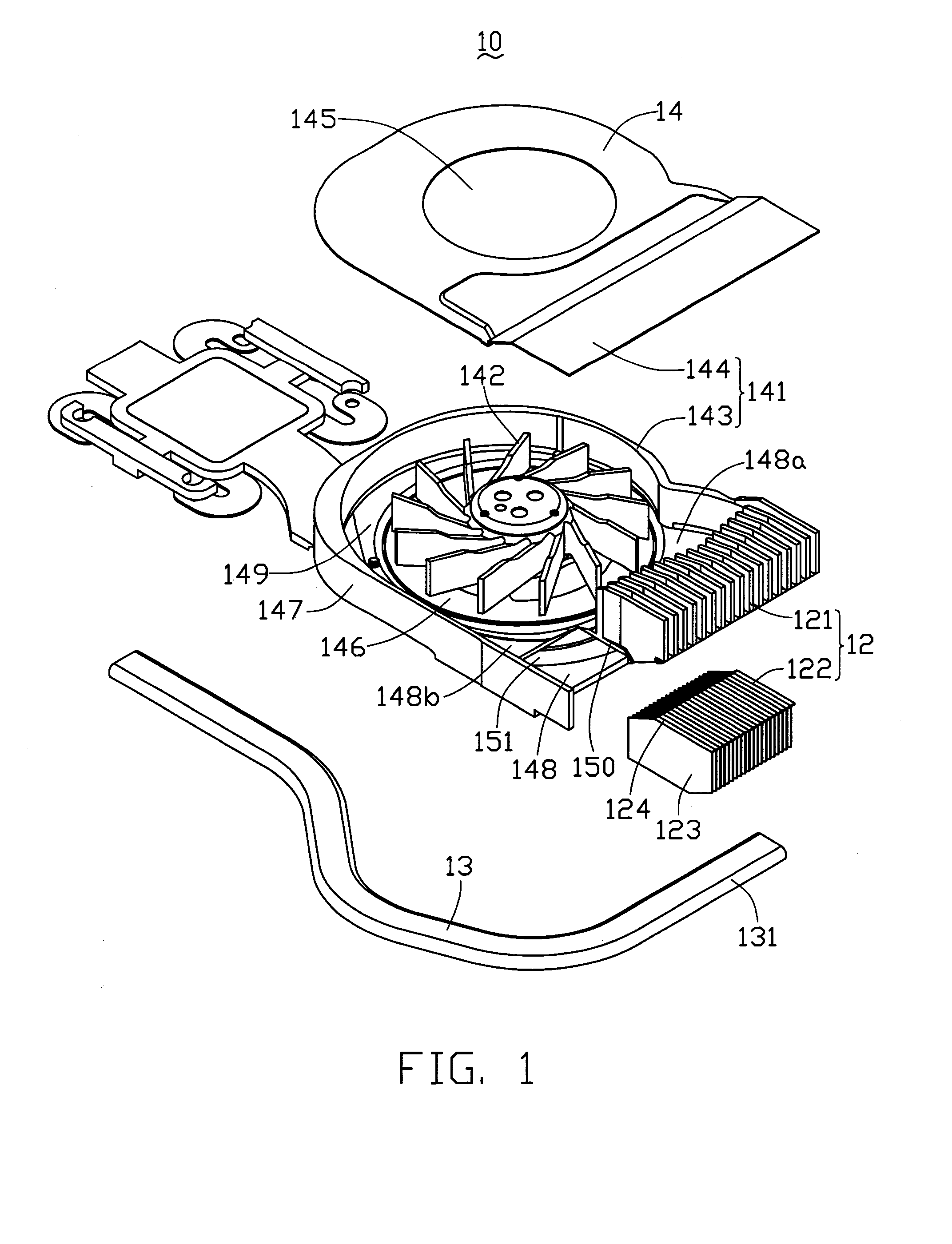
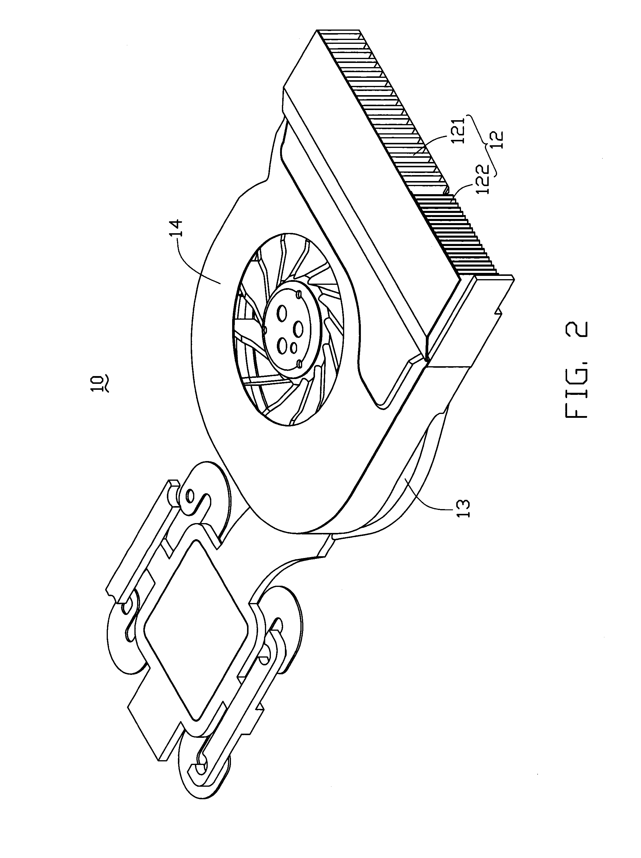
[0014]FIGS. 1 to 3 show a heat dissipation apparatus 10 according to a preferred embodiment of the present invention. The heat dissipation apparatus 10 includes a fin assembly 12, an arc shaped flat heat pipe 13 connecting the fin assembly 12 with a heat-generating electronic component (not shown) to transfer heat therebetween, and a heat-dissipating fan 14 for providing an airflow flowing through the fin assembly 12 to take the heat away.

[0015]The heat-dissipating fan 14 is a centrifugal blower which enables the airflow to have a high air pressure. The heat-dissipating fan 14 includes a casing 141, a stator (not shown) mounted in the casing 141, and a rotor including a plurality of blades 142 rotatably disposed around the stator for generating an airflow.

[0016]The casing 141 includes a bottom housing 143 and a top cover 144 mounted on the bottom housing 143. The top cover 144 is a plate, which defines an air inlet 145 at a middle portion thereof. The bottom housing 143 includes a f...


PUM


Abstract

A heat dissipation apparatus (10) includes a heat-dissipating fan (14) and a fin assembly (12). The heat-dissipating fan includes a casing (141) and a plurality of blades (142) rotatably received in the casing. The casing defines an air outlet (148) through which an airflow generated by the blades flows. The air outlet has a front side (148b) and a rear side (148a). The airflow first reaches the front side and then flows towards the rear side. The fin assembly is arrangepd at the air outlet of the fan, and includes a plurality of first fins (121) adjacent to the rear side of the air outlet and a plurality of second fins (122) adjacent to the front side of the air outlet. The first fins are integrally formed with the casing of the fan, whilst the second fins consist of a stack of individually formed fins.

Description

BACKGROUND OF THE INVENTION[0001]1. Field of the Invention[0002]The present invention relates generally to a heat dissipation apparatus, and more particularly to a heat dissipation apparatus for dissipating heat generated by electronic components.[0003]2. Description of Related Art[0004]In nowadays, heat dissipation apparatuses are arranged in electronic products such as computers in order to dissipate heat generated by heat-generating electronic components such as CPUs. The heat dissipation apparatus includes a fan and a fin assembly integrally formed at an air outlet of the fan. The fin assembly thermally connects with the CPU to absorb heat therefrom. The fan provides an airflow flowing through the fin assembly to take the heat away so as to keep the CPU at a normal working temperature.[0005]However, due to the rapid development of the electronics industry, heat dissipation apparatuses with integrally formed fin assemblies can not satisfy the heat dissipation requirements of high...

Claims


Application Information

Patent Timeline
IPC IPC(8): H05K7/20
CPCG06F1/20H05K7/20172G06F2200/201
Inventor HWANG, CHING-BAIZHANG, JIE
Owner HON HAI PRECISION IND CO LTD
Why Eureka
Try Eureka