
Broken Rail Detection System

a detection system and rail technology, applied in railway signalling, railway signalling, railway profile gauges, etc., can solve the problems of numerous deficiencies in broken rail detection systems, and large amount of wires required

Inactive Publication Date: 2008-05-08
BOMBARDIER TRANSPORTATION GMBH
View PDF4 Cites 73 Cited by
  • Summary
  • Abstract
  • Description
  • Claims
  • Application Information

AI Technical Summary

Problems solved by technology

Due to excessive use, and environmental conditions such as extreme temperatures, railway tracks can deteriorate and eventually break.
Unfortunately, such broken rail detection systems are plagued with numerous deficiencies.
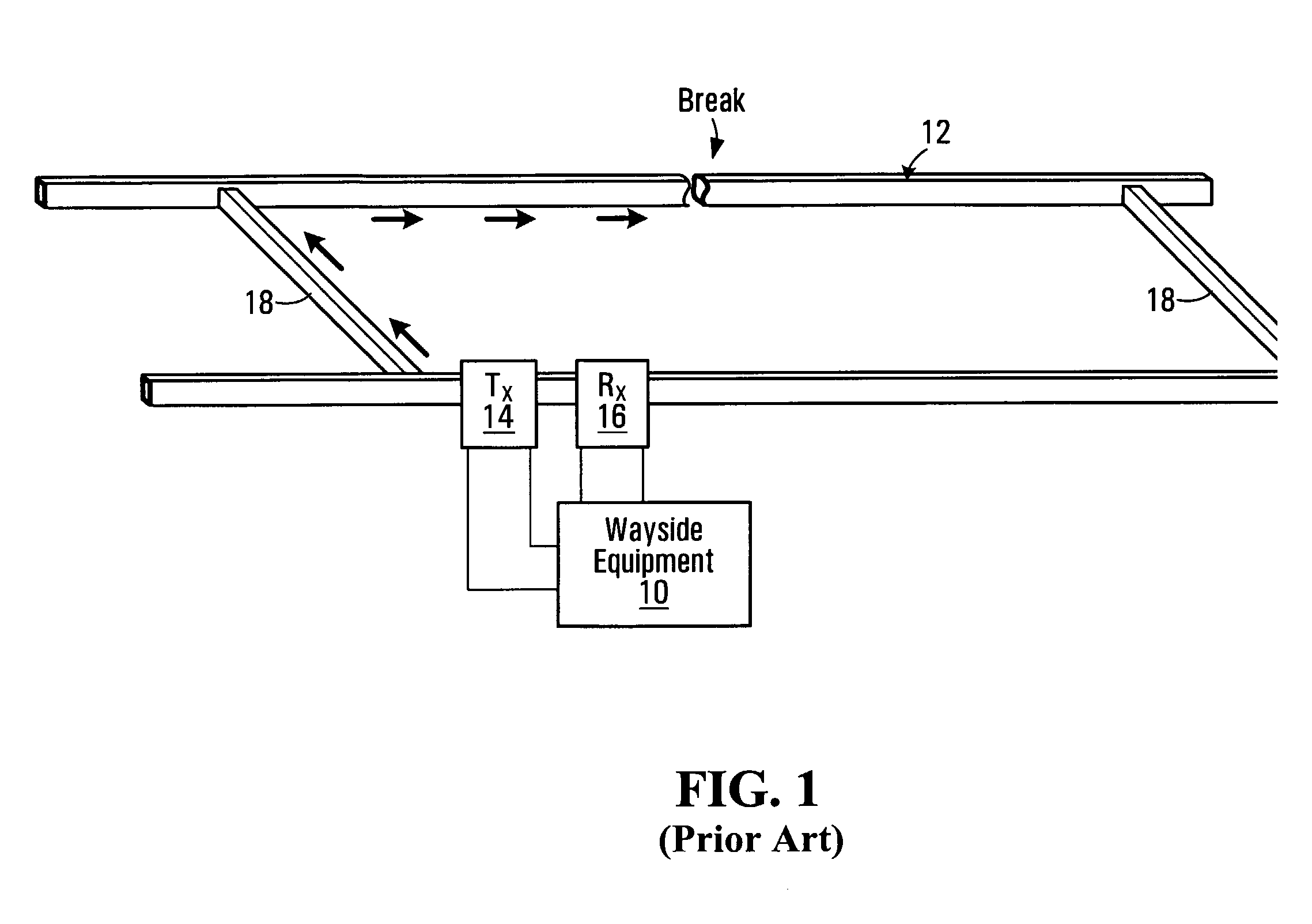
A first such deficiency is that a significant amount of wire is required in order to connect the transmitters 14 and the receivers 16 to the wayside equipment 10.
This is not only costly, but is also difficult to maintain.
A further deficiency with existing systems is that when trains are running on the track, the broken rail detection system cannot always be used.
As such, if a train is on the track, it will short out the section of track between itself and the shunt.
As such, the wayside equipment will not be able to accurately perform broken rail detection on the rails when there are trains travelling thereon.
The more trains that are running on the track, the less the system can accurately perform broken rail detection, since the trains cause shunting of so much of the track.

Method used


Image

  • Broken Rail Detection System
  • Broken Rail Detection System
  • Broken Rail Detection System

Examples


Embodiment Construction

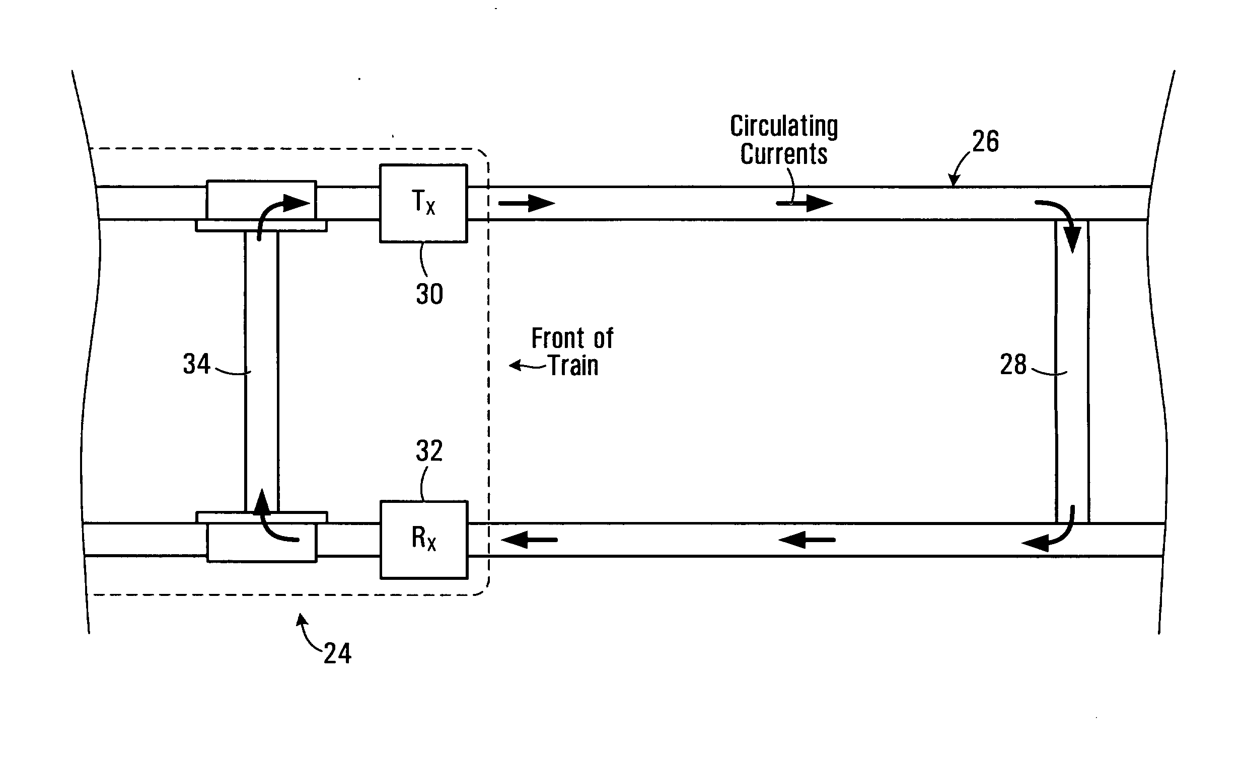
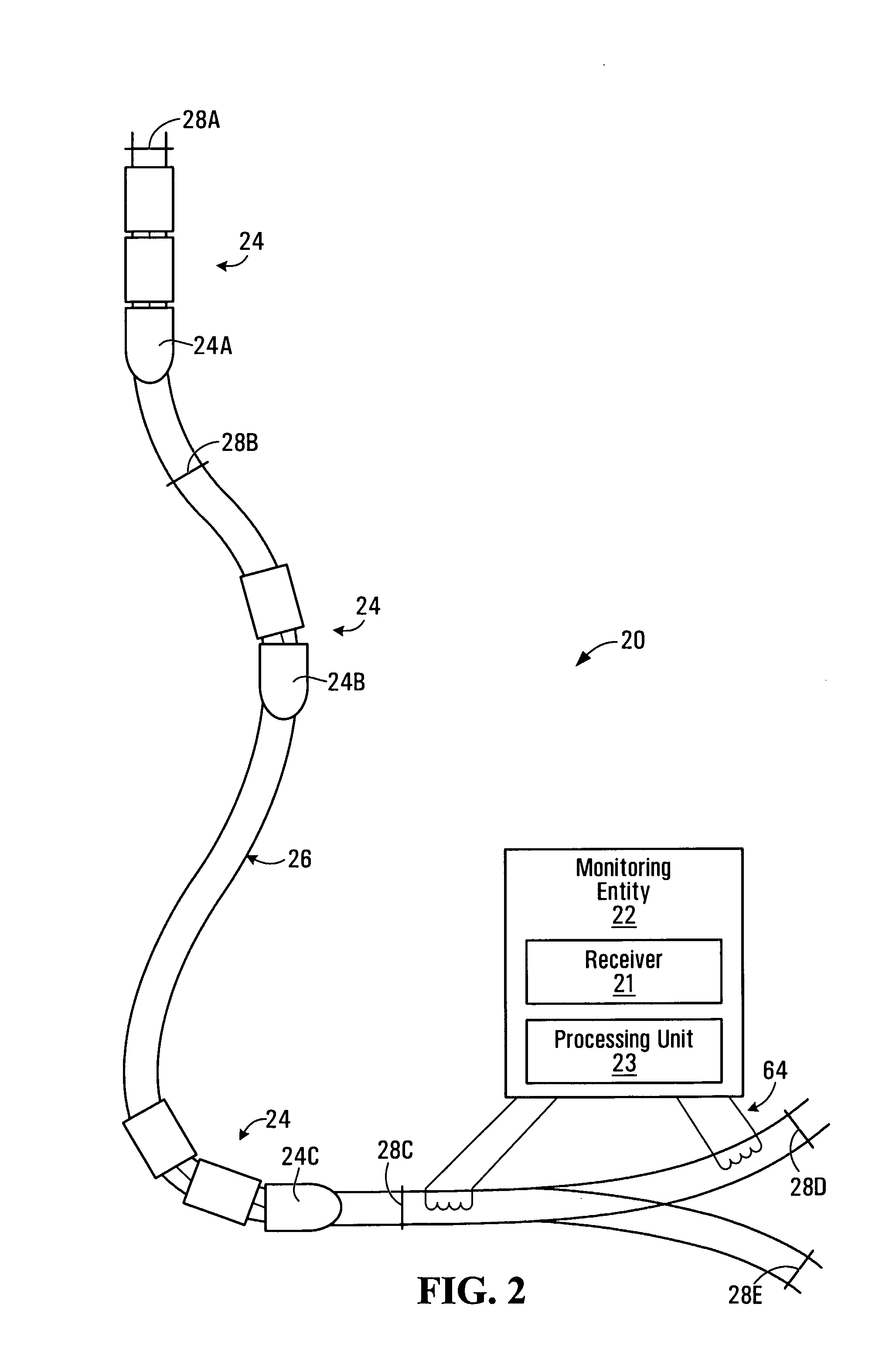
[0021]Shown in FIG. 2 is a broken rail detection system 20 in accordance with a non-limiting example embodiment of the present invention. The broken rail detection system 20 includes a monitoring entity 22 that is in communication with one or more locomotives 24. For the purposes of the following description, three locomotives 24a, 24b and 24c are included in the schematic diagram of FIG. 2. It should, however, be understood that any number of locomotives 24 can be included as part of the broken rail detection system 20, without departing from the spirit of the present invention.

[0022]The monitoring entity 22 is responsible for monitoring the condition of the railway track 24 in a predefined area or region in order to determine, among other things, whether the rails in that region include a break. The predefined area or region may be based on a certain length of railway track (i.e., 100 miles of track, for example) or based on a certain geographical area.

[0023]The monitoring entity ...


PUM


Abstract

A system is for performing broken rail detection on a railway track. The system includes at least one locomotive and a monitoring entity. Each locomotive includes a receiver for receiving a track signal that is circulating in the railway track and a processing unit that is in communication with the receiver. The processing unit is operative for detecting a characteristic of the track signal and generating a signal indicative of a potential broken rail in response to a change in the characteristic of the track signal. The locomotive further includes a wireless transmitter for transmitting the signal indicative of a potential broken rail over a wireless communication link. The monitoring entity includes a receiver for receiving the signal indicative of a potential broken rail and a processing unit for detecting a broken rail at least in part on the basis of the signal indicative of a potential broken rail from the locomotive.

Description

CROSS-REFERENCE TO RELATED APPLICATIONS[0001]The present application claims the benefit of U.S. Provisional Patent Application Ser. No. 60 / 635,003, filed on Dec. 13, 2004, which is expressly incorporated herein in its entirety by reference thereto.FIELD OF THE INVENTION[0002]The present invention relates to the field broken rail detection systems, and more particularly to detection systems that use voltage and / or current signals circulating in the railway track for detecting broken rails.BACKGROUND INFORMATION[0003]In order to ensure the safety of railway transportation, it is not only important to keep the locomotives in good working condition, it is also important to keep the railway tracks themselves in good working condition. Due to excessive use, and environmental conditions such as extreme temperatures, railway tracks can deteriorate and eventually break. It is therefore important to monitor the condition of the railway tracks in order to ensure that they do not include breaks...

Claims


Application Information

Patent Timeline
Patent Type & Authority Applications(United States)
IPC IPC(8): B61K9/10
CPCB61K9/10B61L3/121B61L23/044
Inventor KARG, KENNETH A.
Owner BOMBARDIER TRANSPORTATION GMBH
Learn More