Ultra-fast ultracapacitor pack/device charger

a technology of ultracapacitors and chargers, applied in electrical storage systems, safety/protection circuits, instruments, etc., can solve the problems of reducing life or failure, and affecting the charge rate of ultracapacitors

Inactive Publication Date: 2008-05-08
DAN J AND DENISE L COSTA 1997 FAMILY TRUST
View PDF26 Cites 26 Cited by
  • Summary
  • Abstract
  • Description
  • Claims
  • Application Information

AI Technical Summary

Problems solved by technology

Because ultracapacitors are sensitive to being charged over their rated voltage, overcharging can result in significantly reduced life or failure.
Another issue in recharging ultracapacitors is in capacitance variance.
Charged ultracapacitors also experience leakage or self-discharge.
This type of balancing has the following limitations: (1) because it takes time to balance all of the cells, the charging cannot be done rapidly .
. . rapid charging of the cells would not allow enough time to ensure proper balancing and some cells in a series string could become over charged; and (2) balancing circuits consume energy and reduce the voltage of every cell to the lowest voltage cell, which wastes energy.
However, if the cells are charged at a current rate that is higher than what the circuit can bypass, the cell could become overcharged.
It can only protect the cell if it can bypass as much current as the cell is being charged by.
This also wastes energy close to the cells rated voltage because a zener does not have a distinct breakdown voltage.
This method consumes a significant amount of energy from the ultracapacitors and balances the cells very slowly.
This slow balancing does not allow the cells to be charged from a low voltage to their maximum voltage rapidly without possibly overcharging one or more of the cells.

Method used


Image

  • Ultra-fast ultracapacitor pack/device charger
  • Ultra-fast ultracapacitor pack/device charger
  • Ultra-fast ultracapacitor pack/device charger

Examples


first embodiment

[0044]The first embodiment is an ultracapacitor charging method for charging a string of ultracapacitor cells. The method comprising the steps of: (1) measuring the voltage of each ultracapacitor cell; (2) determining a maximum voltage level of each ultracapacitor cell; (3) determining which ultracapacitor cell has the largest voltage; (4) charging said string of ultracapacitor cells through use of a charger, said charger connected to a voltage source; (5) monitoring the voltage of the ultracapacitor cell having the largest voltage; and, (6) stopping the charging said string when the ultracapacitor cell with the largest voltage reaches its maximum voltage level.

[0045]It is preferred that the method further comprise: (1) first connecting said string of ultracapacitor cells to said charger, (2) last disconnecting said string of ultracapacitor cells from said charger. It is further preferred that the voltage of each ultracapacitor cell is monitored during the charging step to determine...

second embodiment

[0046]A second embodiment is a method of charging a string of ultracapacitors comprising the following steps: (1) connecting a string of ultracapacitors to a charger, said charger connected to a voltage source; (2) measuring the voltage of each of the ultracapacitors in said string; (3) charging said string of ultracapacitors using said charger; (4) monitoring the voltage of each ultracapacitor; (5) determining which ultracapacitor cell has the largest voltage; (6) monitoring the voltage of the ultracapacitor cell with the largest voltage during charging; (7) stopping charging of said string of ultracapacitors when the ultracapacitor cell with the largest voltage reaches its maximum voltage; and, (8) disconnecting said charger from said string of ultracapacitors. Further steps optionally including: (9) calculating the total string voltage by summing the voltages of said ultracapacitor cells, (10) following a current (charging) profile based upon the total string voltage; and (11) mo...

third embodiment

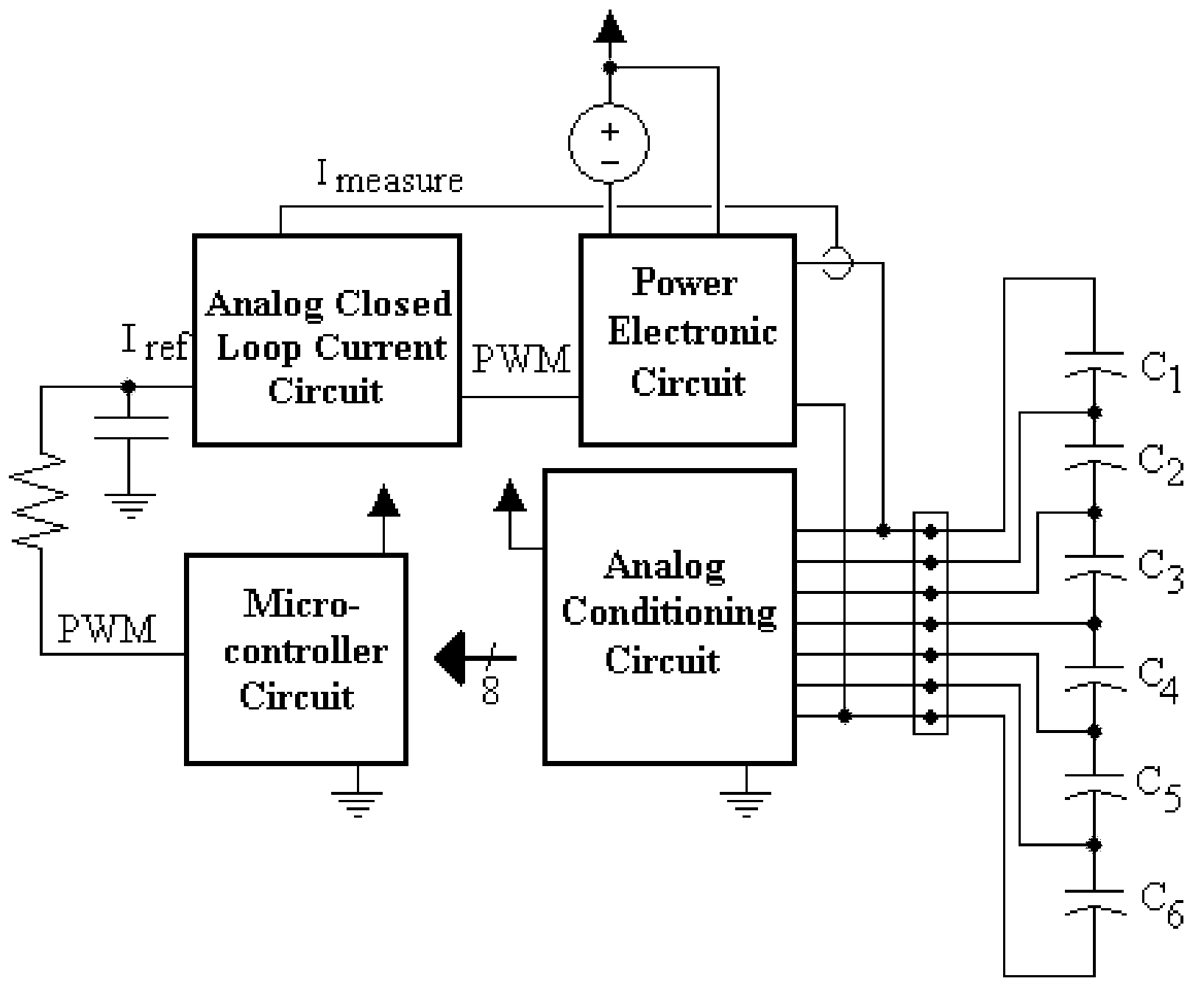
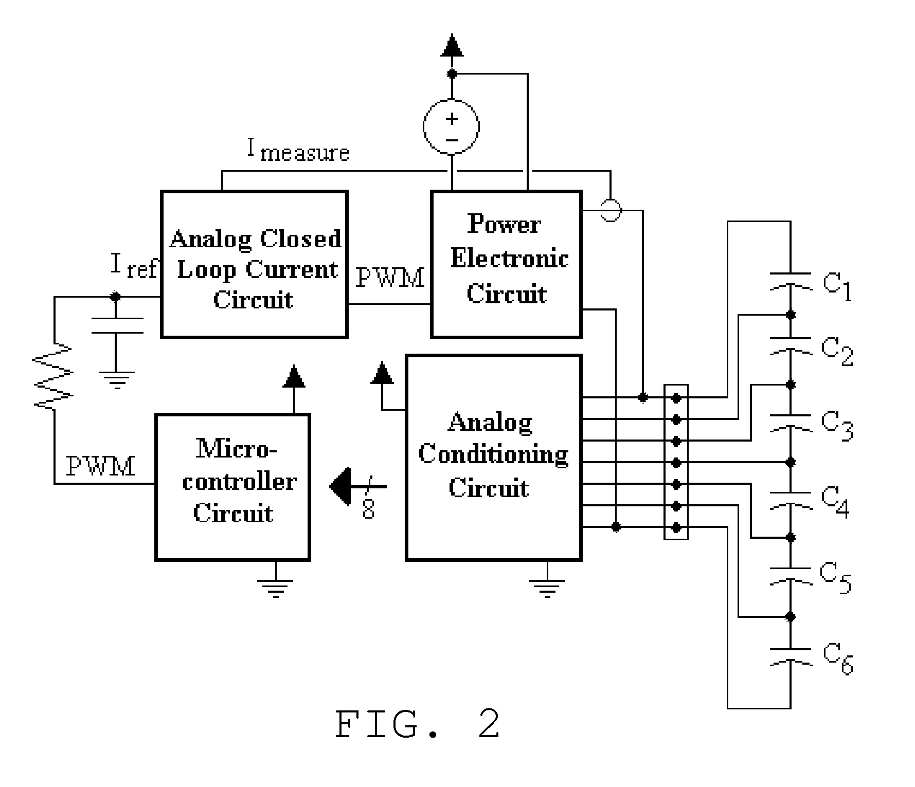
[0047]A third embodiment being a charger for charging a string of ultracapacitors. The charger comprising: (1) a voltage source; (2) a MCU, said MCU measuring the voltage of each ultracapacitor cell via an analog circuit during charging to determine which ultracapacitor cell has the largest voltage, said MCU commanding current to said string of ultracapacitors based on the measured voltages, said MCU monitoring the voltage of the ultracapacitor cells and when the ultracapacitor cell with largest voltage reaches its maximum voltage the MCU commands the voltage source to stop charging the ultracapacitor string; and (3) a first analog circuit, said first analog circuit for allowing the MCU to measure the voltage of each ultracapacitor cell, said first analog circuit measuring the difference between the positive and negative terminals of each ultracapacitor in said string and outputting a signal proportional to the voltage to the MCU. Optionally the charger could comprise a second analo...


PUM


Abstract

A charger for ultracapacitors that allows many ultracapacitors, that may be connected in several different configurations, to be charged from a very low voltage to their rated voltage very rapidly without cell damage. The charger also allows for the detection of failed cells.

Description

FIELD OF THE INVENTION[0001]The present invention generally relates to ultracapacitors, and more particularly to chargers for ultracapacitors.BACKGROUND OF THE INVENTION[0002]Ultracapacitors, also known as double layer capacitors, DLCs, supercapacitors or psuedocapacitors are devices that store electrical energy. Ultracapacitor are increasingly being used to power consumer products, automotive energy storage systems, military applications, etc. as the sole energy storage device or they in combination with batteries.[0003]After their charge is depleted, ultracapacitors are recharged. Ultracapacitors have to go through a fairly large voltage swing to be used as an energy storage device and must be charged carefully to prevent damage. Because ultracapacitors are sensitive to being charged over their rated voltage, overcharging can result in significantly reduced life or failure.[0004]Another issue in recharging ultracapacitors is in capacitance variance. The capacitance of an ultracapa...

Claims


Application Information

Patent Timeline
Patent Type & Authority Applications(United States)
IPC IPC(8): H02J15/00G01R19/25
CPCG01R31/3658H02J7/0018H02J7/345H02J7/0026H02J7/0024G01R31/396H02J7/00302
Inventor CEGNAR, ERIK J.
Owner DAN J AND DENISE L COSTA 1997 FAMILY TRUST
Why Eureka
Try Eureka