Systems and methods for a head-mounted display

a technology of video display and head-mounted display, which is applied in the field of system and method of head-mounted video display, can solve the problems of limited acceptance of virtual reality systems, distortion of visual perception, and increased head movements to scan a visual environment,

Inactive Publication Date: 2008-05-08
RAZER ASIA PACIFIC
View PDF11 Cites 109 Cited by
  • Summary
  • Abstract
  • Description
  • Claims
  • Application Information

AI Technical Summary

Benefits of technology

[0017] One embodiment of the present invention is a head-mounted display with an upgradeable field of view. The head-mounted display includes an existing lens, an existing display, an added lens, and an added display. The existing display is imaged by the existing lens and the added display is imaged by the added lens. The existing lens and the existing display are installed in head-mounted display at the time of manufacture of the head-mounted display. The added lens and the added display are installed in the head-mounted display at a time later than the time of manufacture. The existing lens and the added lens are positioned relative to one another as though each of the lenses is tangent to a surface of a first sphere having a center that is located substantially at a center of rotation of an eye of a user. The existing display and the added display are positioned relative to one another as though each of the displays is tangent to a surface of a second sphere having a radius larger than the first sphere's radius and having a center that is located at the center of rotation of the eye. The added lens and the added display upgrade the field of view of the head-mounted display.
[0018] Another embodiment of the present invention is a method for extending the field of view of a head-mounted display. An added lens is positioned in the head-mounted display relative to an existing lens as though each of the lenses is tangent to a surface of a first sphere having a center that is located substantially at a center of rotation of an eye of a user of the head-mounted display. An added display is positioned in the head-mounted display relative to an existing display as though each of the displays is tangent to a surface of a second sphere having a radius larger than the first sphere's radius and having a center that is located at the center of rotation of the eye. The added lens and the added display extend the field of view of the head-mounted display. A first image shown on the existing display is aligned with a second image shown on the added display using a processor and an input device. The processor is connected to the head-mounted display and the input device is connected to the processor. Results of the alignment are stored in a memory connected to the processor.
[0020] Another embodiment of the present invention is a telepresence system. The telepresence system includes a head-mounted display, a communications network, and an image sensor array. The head-mounted display includes a plurality of lens and a plurality of displays. The plurality of lenses are positioned relative to one another as though each of the lenses is tangent to a surface of a first sphere having a center that is located substantially at a center of rotation of an eye of a user. The plurality of displays are positioned relative to one another as though each of the displays is tangent to a surface of a second sphere having a radius larger than the first sphere's radius and having a center that is located at the center of rotation of the eye. Each of the displays corresponds to at least one of the lenses, and is imaged by the corresponding lens. The image sensor array includes a plurality of image sensor lenses and a plurality of image sensors. The plurality of image sensor lenses are positioned relative to one another as though each of the lenses is tangent to a surface of a third sphere. The plurality of image sensors are positioned relative to one another as though each of the image sensors is tangent to a surface of a fourth sphere having a radius larger than the third sphere's radius and having a center substantially the same as a center of the third sphere. Each of the image sensors corresponds to at least one of the image sensor lenses, and is imaged by the corresponding image sensor lens. The image sensor array is connected to the head-mounted display by the communications network. A second image sensor array can be added to the telepresence system so that there is one image sensor array per eye. An image sensor array per eye can provide a stereo telepresence experience.

Problems solved by technology

One would expect, and a few studies confirm, that visual field restrictions (e.g., with head-mounted telescopes) result in a limited range of eye movements and increased head movements to scan a visual environment.
Forcing a user of a virtual display system used as a design and development tool to adapt his or her behavior when working in a particular virtual environment could lead to distortions of visual perception and misjudgment on important design decisions.
Simulator sickness is a serious problem that has limited the acceptance of virtual reality systems.
However, because video displays have a fixed number of pixels, magnification of the display to increase field of view is done at the expense of visual resolution (i.e., visual angle of the display pixels).
This is because magnification of the display also increases magnification of individual display pixels, which results in a trade-off between angular resolution and field of view for HMDs that use single displays.
The FIHMD could not provide the quality and usability desired in such an HMD, and the seams between the optics and the optics themselves was a particularly large problem.
The FIHMD had limitations imposed by its use of the VIM optics and the requirement for adequate eye relief to accommodate spectacles.
Because of this choice of centers, the FIHMD had problems with visibility of seams between the displays and with display alignment.

Method used


Image

  • Systems and methods for a head-mounted display
  • Systems and methods for a head-mounted display
  • Systems and methods for a head-mounted display

Examples


Embodiment Construction

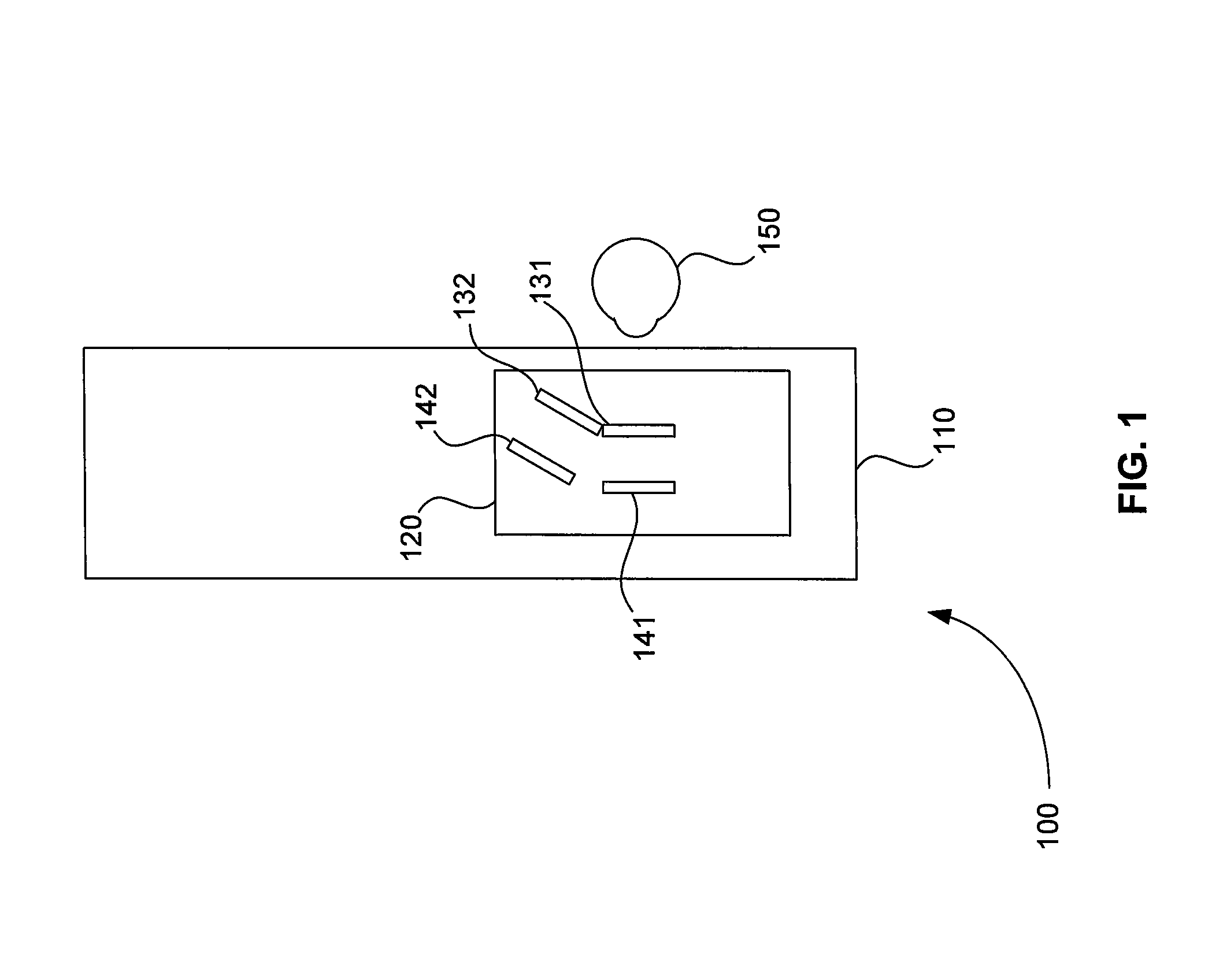
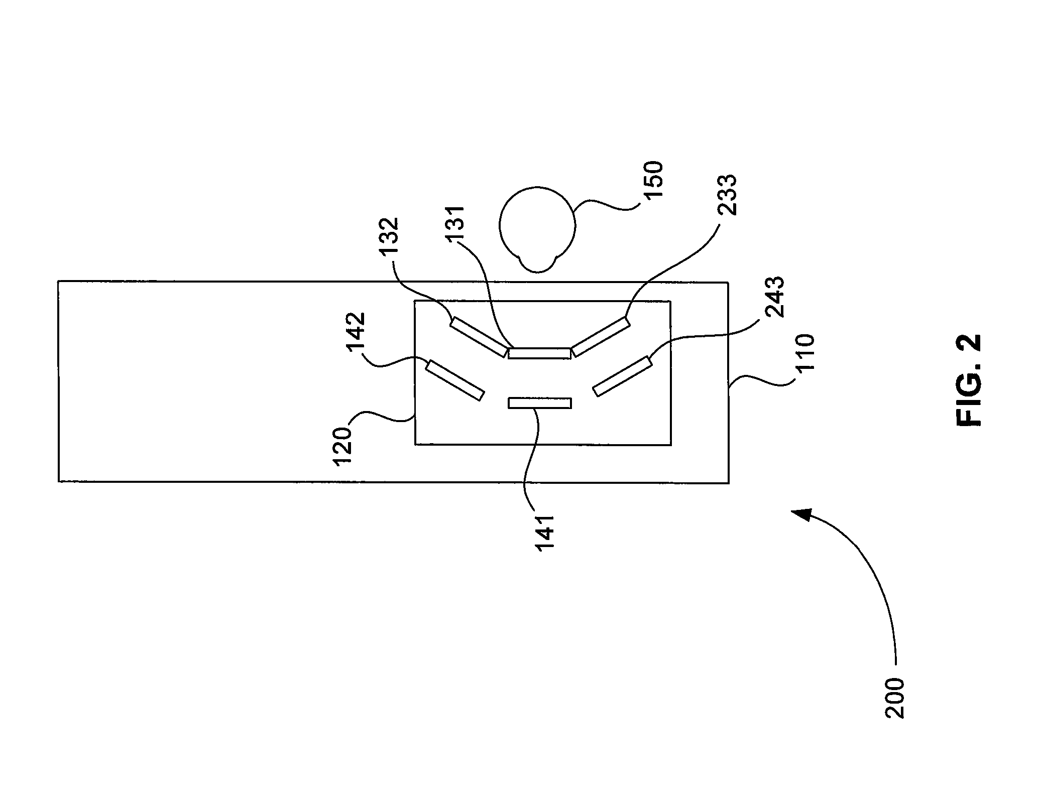
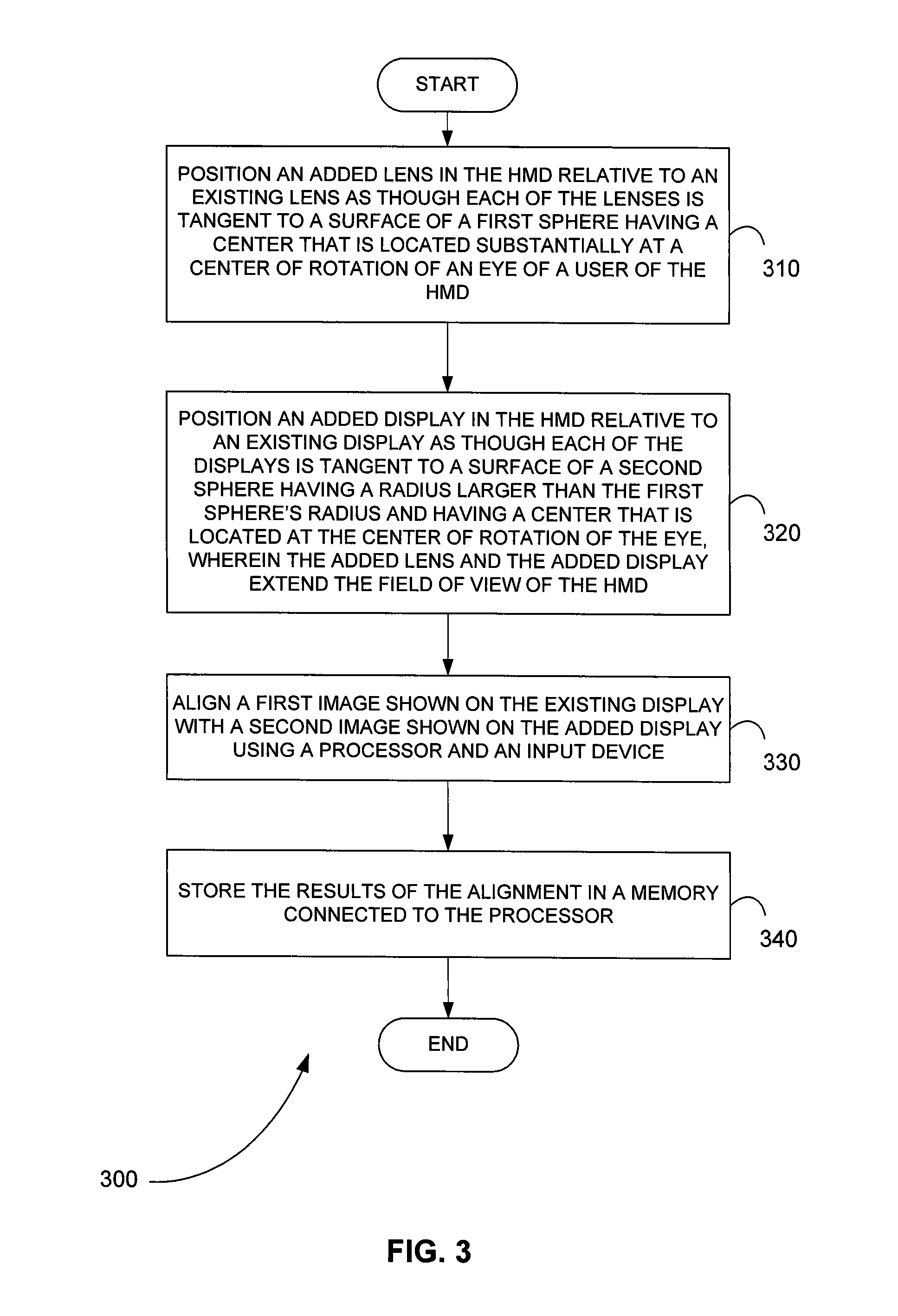
[0028] A tiled multiple display HMD is described in U.S. Pat. No. 6,529,331 (“the '331 patent”), which is herein incorporated by reference in its entirety. The HMD of the '331 patent solved many of the problems of the FIHMD, while achieving both high visual resolution and a full field of view (FOV). The HMD of the '331 patent used an optical system in which the video displays and corresponding lenses were positioned tangent to hemispheres with centers located at the centers of rotation of a user's eyes. Centering the optical system on the center of rotation of the eye was the principal feature of the HMD of the '331 patent that allowed it to achieve both high fidelity visual resolution and a full FOV without compromising visual resolution.

[0029] The HMD of the '331 patent used a simpler optical design than that used by the FIHMD. The HMD of the '331 patent used an array of lens facets that were positioned tangent to the surface of a sphere. The center of the sphere was located at a...


PUM


Abstract

A head-mounted display with an upgradeable field of view includes for at least one eye an existing lens, an existing display, an added lens, and added display. The existing lens and the added lens are positioned relative to one another as though each of the lenses is tangent to the surface of a first sphere having a center that is located substantially at a center of rotation of the eye. The existing display and the added display are positioned relative to one another as though each of the displays is tangent to a surface of a second sphere having a radius larger than the first sphere's radius and having a center that is located at the center of rotation of the eye. A head mount for the head-mounted display includes two parallel rails, one or more brow pads, one or more top pads, and one or more back pads.

Description

CROSS-REFERENCE TO RELATED APPLICATION [0001] This application claims the benefit of U.S. Provisional Patent Application Ser. No. 60 / 856,021 filed Nov. 2, 2006 and U.S. Provisional Patent Application Ser. No. 60 / 944,853 filed Jun. 19, 2007, which are herein incorporated by reference in their entireties.BACKGROUND OF THE INVENTION [0002] 1. Field of the Invention [0003] Embodiments of the present invention relate to systems and methods for head-mounted video displays for presenting virtual and real environments. More particularly, embodiments of the present invention relate to systems and methods for presenting and viewing virtual and real environments on a head-mounted video display capable of providing a full field of view and including an array of display elements. [0004] 2. Background Information [0005] Traditionally, displays for virtual environments have been used for entertainment purposes, such as presenting the environments for the playing of various video games. More recent...

Claims


Application Information

Patent Timeline
Patent Type & Authority Applications(United States)
IPC IPC(8): G09G5/00
CPCG02B27/0172G06F3/1446G02B2027/0123G02B27/0176
Inventor BROWN, LAWRENCE G.BOGER, YUVAL S.SHAPIRO, MARC D.
Owner RAZER ASIA PACIFIC
Why Eureka
Try Eureka