Fluid mixer and mixing element member

a technology of fluid mixer and mixing element, which is applied in the direction of mixing, emulsification, transportation and packaging, etc., can solve the problems of fluid mixer not being used and fresh fluid not being supplied, and achieve the effect of efficient mixing and increasing the mixing ra

Inactive Publication Date: 2008-05-08
ANEMOS
View PDF12 Cites 8 Cited by
  • Summary
  • Abstract
  • Description
  • Claims
  • Application Information

AI Technical Summary

Benefits of technology

[0010]According to an embodiment of the present invention, there is provided a fluid mixer and a mixing element member in which different types of fluids may be efficiently mixed.
[0036]According to the fluid mixer of an embodiment according to the present invention, since different types of fluids are supplied to the mixing member using separate passages, the fluids are not cured in the passages and may be efficiently mixed.
[0037]According to the mixing element member of an embodiment of the present invention, since different types of fluids are efficiently mixed in the divider, the fluids passing through the mixing member may be mixed at an increased mixing rate.

Problems solved by technology

In addition, since a fluid is cured in the inlet passage 122, a fresh fluid may not be supplied and the fluid mixer may not be used, disadvantageously.

Method used


Image

  • Fluid mixer and mixing element member
  • Fluid mixer and mixing element member
  • Fluid mixer and mixing element member

Examples


Embodiment Construction

[0048]An embodiment of the fluid mixer of the present invention will be described with reference to the drawings; however, the present invention is not limited to the following embodiment. The mixing element member of an embodiment according to the present invention will also be described together with the fluid mixer.

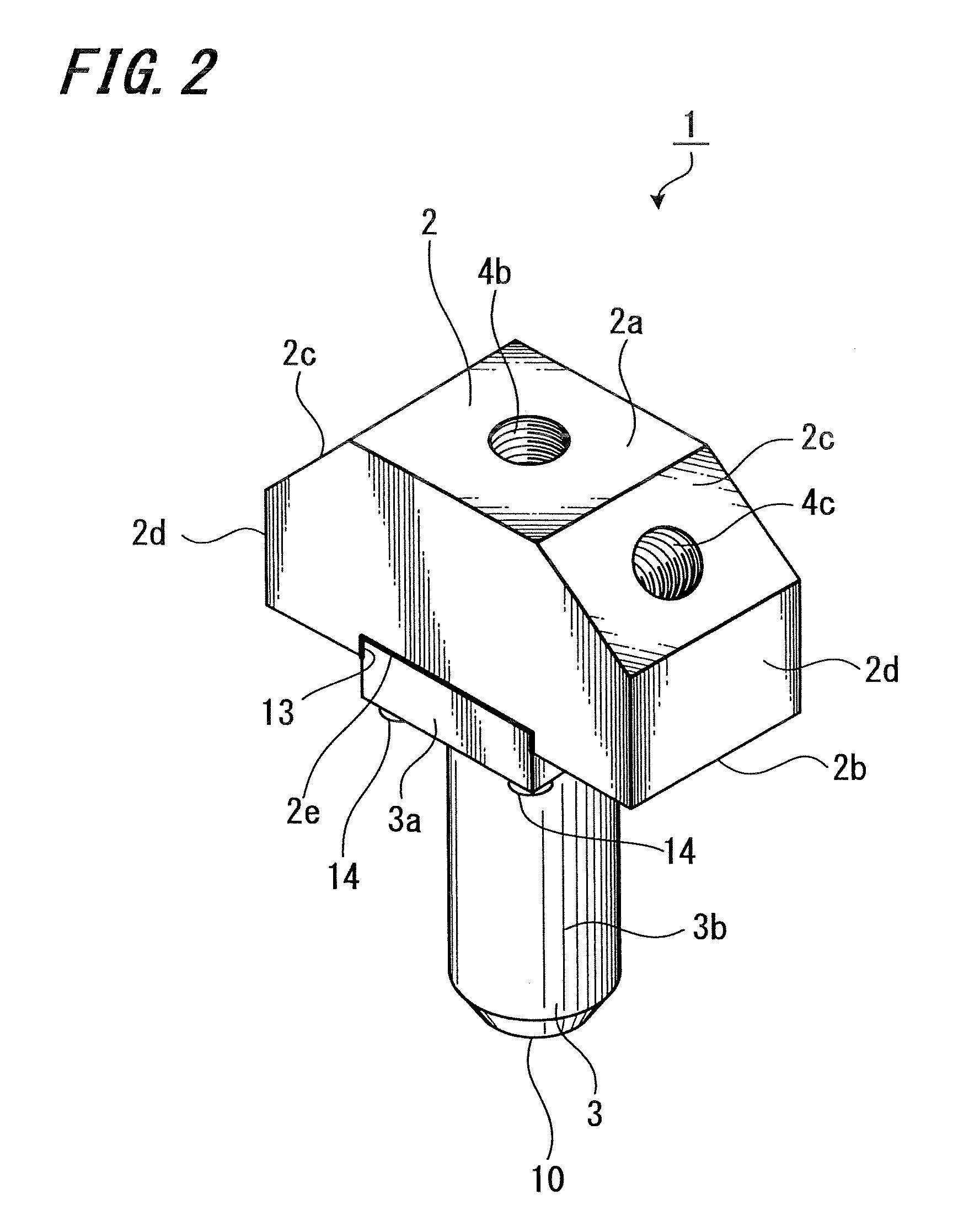
[0049]FIG. 2 shows an oblique view of a fluid mixer according to an embodiment of the present invention.

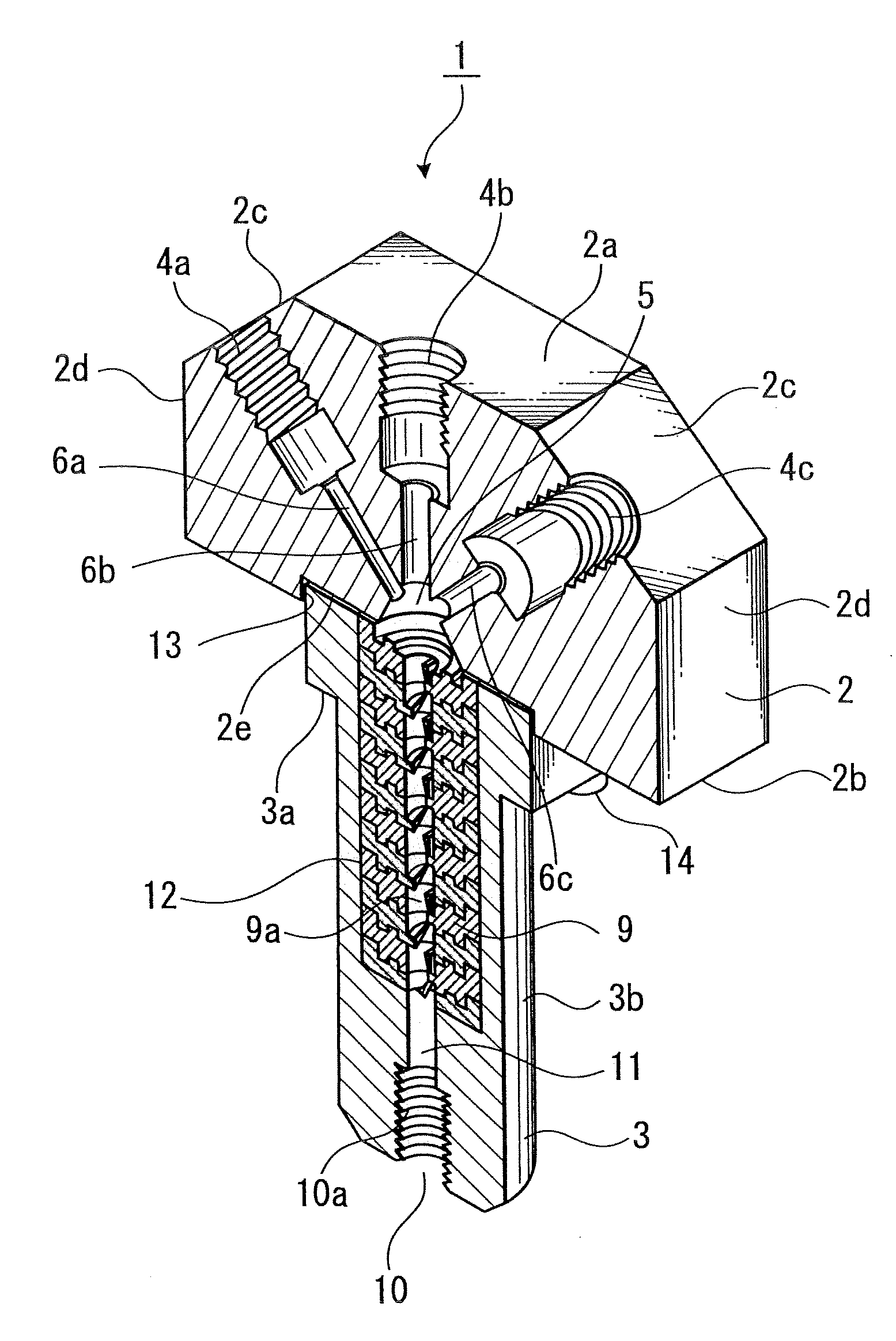
[0050]As shown in FIG. 2, the fluid mixer 1 according to the present embodiment is formed by a top section 2 and a holder section 3.

[0051]The top section 2 has a shape in which a slope of a solid trapezoid member is cut at right angles to a bottom surface. In the top section 2 are formed an upper surface 2a; a bottom surface 2b; side surfaces 2c opposed to each other with respect to a center cutting-plane line between the upper surface 2a and the bottom surface 2b; and side surfaces 2d opposed to each other with respect to the center cutting-plane line between the up...


PUM

PropertyMeasurementUnit
volumeaaaaaaaaaa
diameteraaaaaaaaaa
diameteraaaaaaaaaa

Abstract

Disclosed is a fluid mixer to mix different fluids, the fluid mixer that includes a top section and a holder section. The top section has a plurality of inlets and a mixing portion communicates with the plurality of inlets. The holder section has a discharge portion that communicates with the mixing portion through a passage and a mixing member to mix the different fluids in the middle of the passage.

Description

CROSS REFERENCES TO RELATED APPLICATIONS[0001]The present invention contains subject matter related to Japanese Patent Application JP 2006-299467 filed in the Japanese Patent Office on Nov. 2, 2006, the entire contents of which being incorporated herein by reference.BACKGROUND OF THE INVENTION[0002]1. Field of the Invention[0003]The present invention relates to a fluid mixer to mix, stir, emulsify, disperse, dissolve, diffuse, and chemically react different types of fluids. The present invention relates to a fluid mixer to mix fluids such as a main agent and a curing agent, for example.[0004]2. Description of the Related Art[0005]Domestic Re-publication of PCT International Application 2000-24502 discloses a static fluid mixer of the related art to perform in-line mixing of different types of fluids, where a plurality of mixing elements are placed in a passage structure (casing) corresponding to a pipe, for example.[0006]FIG. 1 shows a schematic cross-sectional view of a fluid mixer...

Claims


Application Information

Patent Timeline
Patent Type & Authority Applications(United States)
IPC IPC(8): B01F15/02
CPCB01F5/0256B29B7/325B01F2005/0636B01F5/0615B01F25/23B01F25/43141B01F25/431971B01F23/40B01F25/00
Inventor KOJIMA, HISAO
Owner ANEMOS
Why Eureka
Try Eureka