Electronic coin bank

a coin bank and electronic technology, applied in the field of coin banks, can solve the problems of reducing the accuracy of counting, affecting and unable to know the total of stored coins, so as to increase the saving interest of users and save manpower and tim

Inactive Publication Date: 2008-05-08
I KIDDO
View PDF4 Cites 19 Cited by
  • Summary
  • Abstract
  • Description
  • Claims
  • Application Information

AI Technical Summary

Benefits of technology

[0012]The third primary objective of the present invention is to provide an electronic coin bank, wherein the user can know the total of the coins stored in the coin bank, the number of each coin and the saving progress at any time without counting artificially. Thereby the present invention can save manpower and time.
[0013]The further primary objective of the present invention is to provide an electronic coin bank which can set the saving goal according to the capability of the user, and implement the saving progress according to the saving goal set by the user. Once reaching a saving progress, the system will provide the rewarding music to the user, in addition to increase the saving interests of the user, the present invention has the effects of rewarding and entertainment.

Problems solved by technology

However, for a long time, the manufacturers mainly focus on the shape of the coin bank, which has some disadvantages described as follows:
Firstly, the conventional coin bank is unable to know the total of the stored coins at any time.
Secondly, if you want to know the total of the stored coins in the coin bank, you must take out all the coins in the coin bank and count artificially, so every time the user have to repeat such action.
Thirdly, since the kinds of the coins are different and the numbers of the coins are too many, the accuracy of counting will be reduced, and the process of counting will cost a lot of time.
Fourthly, the pure changing of the shape of the coin bank is unable to produce user's interests, and after a long time, the user will throw the coin bank away.

Method used


Image

  • Electronic coin bank
  • Electronic coin bank
  • Electronic coin bank

Examples


first embodiment

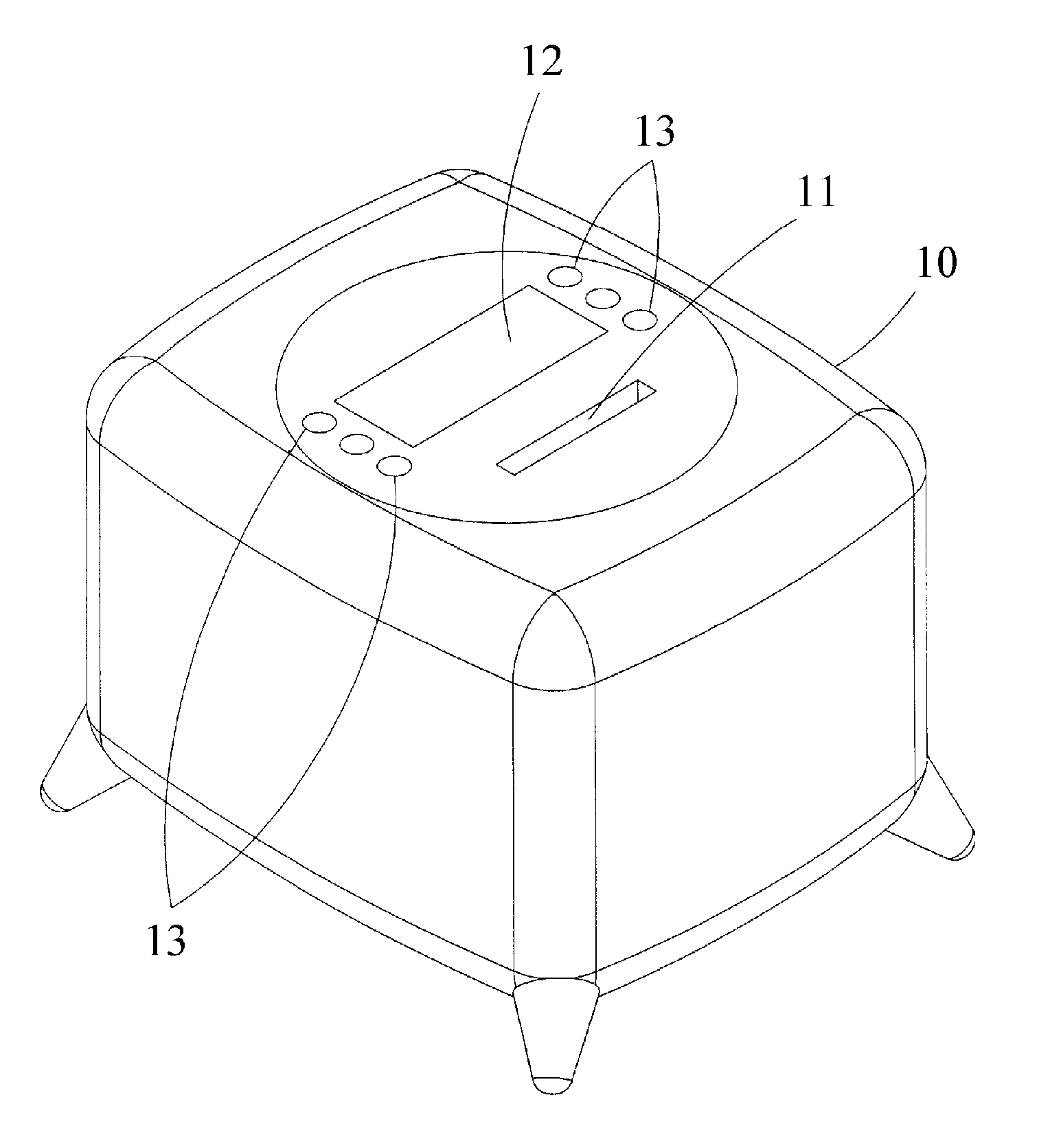
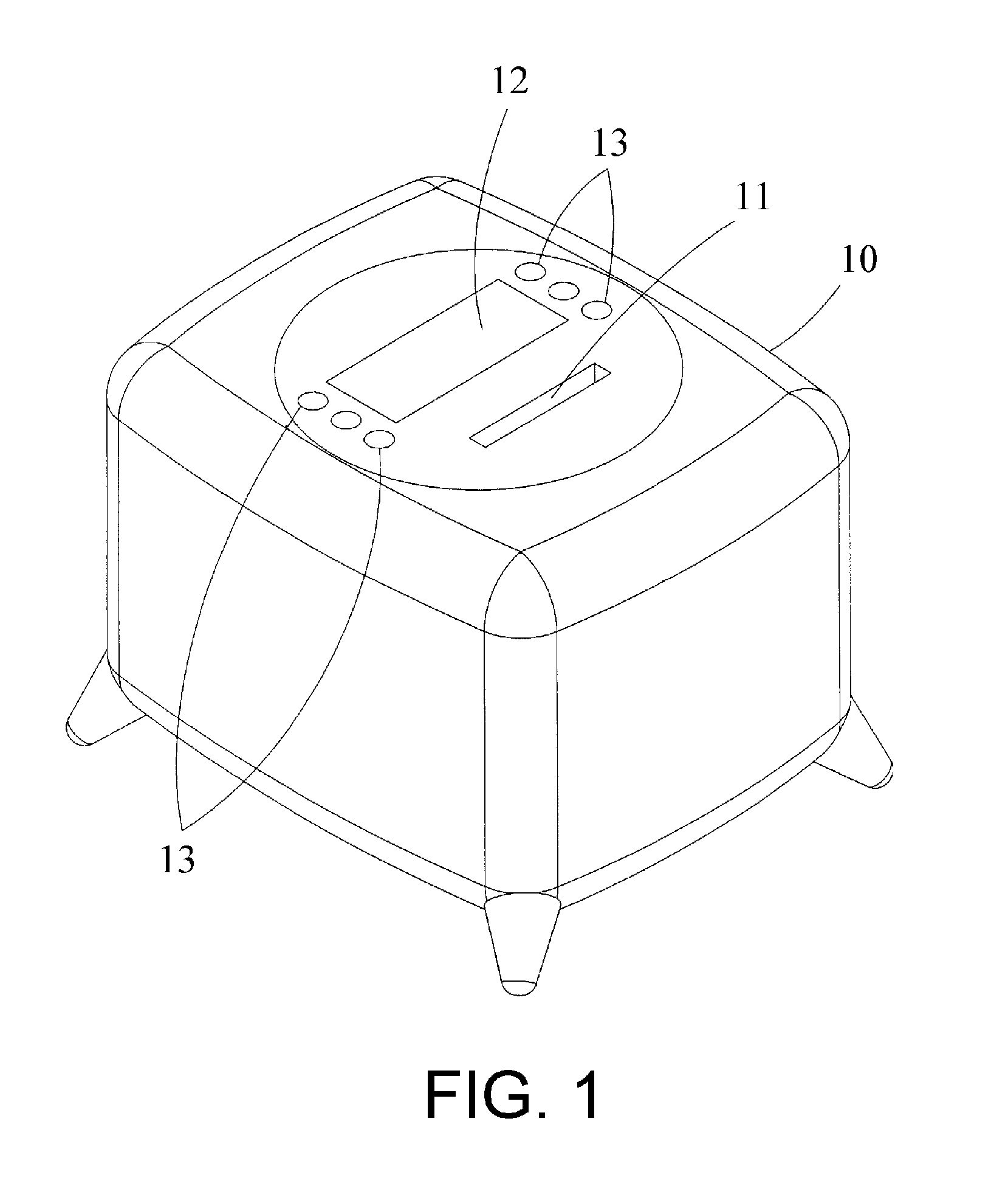
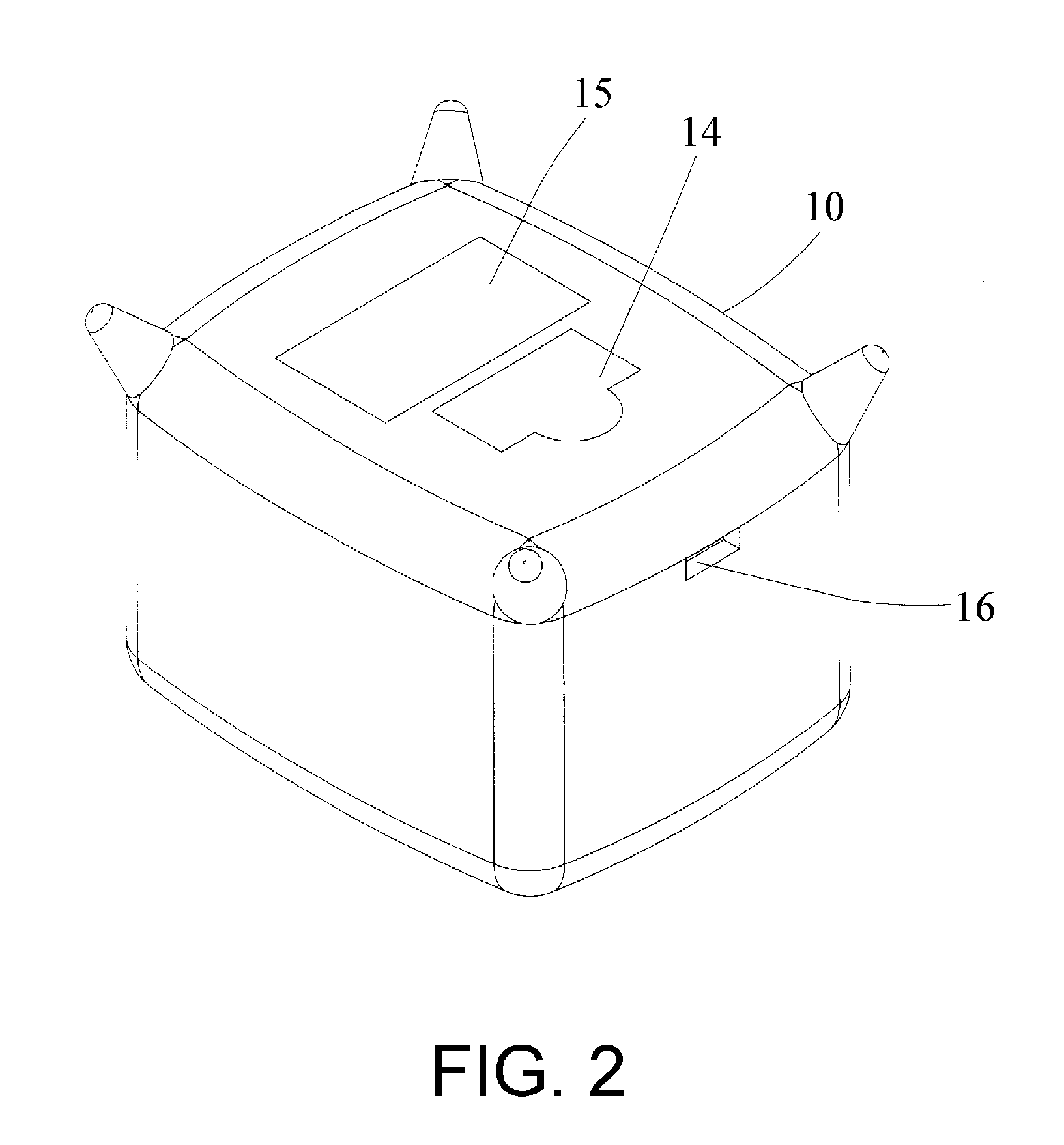
[0029]Referring to FIGS. 1 and 2, an electronic coin bank in accordance with the present invention comprises a coin bank 10, a coin-throwing device 20 (not shown) and a circuit structure 30 (not shown). The coin bank 10 is provided for collecting coins 40 (not shown), an upper surface of the coin bank 10 is defined with a hole 11, a displaying panel 12 and a plurality of setting buttons 13 are disposed adjacent to the hole 11, and the bottom of the coin bank 10 is formed with a hole 141 (not shown) having a cover 14, a battery container 15 and a transmission hole 16. The coin-throwing device 20 (not shown) and the circuit structure 30 (not shown) are mounted in the coin bank 10 that are located correspondingly to the hole 11, and the coin-throwing device 20 is electrically connected to the circuit structure 30, such that the circuit structure 30 can receive the signals of the coin-throwing device 20. The displaying panel 12 and the setting buttons 13 of the coin bank 10 are electric...

second embodiment

[0032]With reference to FIG. 6, an electronic coin bank in accordance with the present invention is shown, wherein one side of the coin-throwing device 20 is disposed with the circuit structure 30, and the position and the shape of the sensing assembly 23 of the coin-throwing device 20 of FIG. 6 is different from that of FIGS. 4 and 5. The sensing assembly 23 is disposed at the side of the bottom of the sliding blocks 22 relative to the surface of the circuit structure 30, and having two electronic brush connecting feet 231 and a brush piece 232, the electronic brush connecting feet 231 are combined to the sliding blocks 22 respectively, and the brush piece 232 is combined to the surface of the circuit structure 30. The electronic brush connecting feet 231 and the brush piece 232 are made of metal and are electrically connected to the circuit structure 30, thus forming the structure of the coin-throwing device 20.

third embodiment

[0033]Referring to FIGS. 7 and 8, an electronic coin bank in accordance with the present invention is shown, when the coin-throwing device 20 is in a normal condition, the distance between the protruded points of the sliding blocks 22 is smaller than the outer diameter of the smallest coin 40 (as shown in FIG. 7). When the coin 40 is thrown into the hole 11 of the coin bank 10 and via the coin-entering hole 211 of the coin-throwing device 20, the sliding blocks 22 will be moved outward by the biggest outer diameter of the coin 4. The sliding blocks 22 are not moved equally, with respect to the change of the reinforcing point when throwing the coin 40, so the total distance of the moving distance of the sliding blocks 22 and the distance between the sliding blocks 22 in the normal condition is the actual moving distance of the sliding blocks 22. At that time, by the connecting method of the electronic brush connecting foot 231 and the brush piece 232, and according to the moving dist...


PUM


Abstract

An electronic coin bank comprises a coin bank, a coin-throwing device and a circuit structure, which changed the single function of saving money of a conventional coin bank into an electronic coin bank, wherein a coin-throwing device is provided for setting the values of the coins and throwing the coins, a circuit structure is provided for setting the stored values, the preparedly stored values, the saving progress, the rewarding music, time and alarm clock, and a transmission connector is connected to a computer. Since the diversifying of the functions and by using the finance-managing software installed in the computer, the children will form a good habit of saving.

Description

BACKGROUND OF THE INVENTION[0001]1. Field of the Invention[0002]The present invention relates to a coin bank, and more particularly to an electronic coin bank which changed the single function of saving money of a conventional coin bank into an electronic coin bank, wherein a coin-throwing device is provided for setting the values of the coins and throwing the coins, a circuit structure is provided for setting the stored values, the preparedly stored values, the saving progress, the rewarding music, time and alarm clock, and a transmission connector is connected to a computer.[0003]2. Description of the Prior Art[0004]A conventional coin bank is hollow-shaped, a suitable position of the coin bank is formed with a coin-entering hole, and another suitable position of the coin bank is formed with a coin-taking hole so as to store the coins in the coin bank and form a good habit of saving. However, for a long time, the manufacturers mainly focus on the shape of the coin bank, which has ...

Claims


Application Information

Patent Timeline
Patent Type & Authority Applications(United States)
IPC IPC(8): A45C1/12
CPCG07D3/16A45C1/12
Inventor LIN, PO-CHI
Owner I KIDDO
Why Eureka
Try Eureka